
The Ultimate Guide to Structured Cabling and Office Network Cabling Solutions
Published:Executive Summary: Structured cabling is the single most consequential infrastructure decision in any office build-out, and the one most often treated as an afterthought. The global structured cabling market reached $20 billion in 2025 and is projected to grow to $21.5 billion in 2026, on its way to $44.5 billion by 2035 at an 8.4 percent CAGR — growth driven not by new construction alone, but by rip-and-replace projects that could have been avoided with a standards-compliant first install.
This guide covers the complete lifecycle of an office cabling plant: the six TIA-568 subsystems, the standards landscape including the 568.1-F consolidation, cable media selection from Cat6a to fiber backbone, MDF/IDF floor design, PoE and Wi-Fi 7 readiness, installation practices that pass certification the first time, and the documentation that protects your warranty for 25 years.
Quick Navigation
- 1 Why Structured Cabling Is the Backbone of Office Networks
- 2 Structured vs Point-to-Point Wiring: The Real Cost Difference
- 3 The Six Subsystems of Structured Cabling
- 4 Standards That Govern Every Installation
- 5 Cable Media: Cat6a Copper and Fiber Backbone
- 6 Designing the Office Floor: MDF, IDF, and Horizontal Cabling
- 7 PoE, Wi-Fi 7, and Smart Building Readiness
- 8 Installation Best Practices That Prevent Certification Failures
- 9 Testing, Certification, and Documentation
- 10 Common Mistakes and the Business Case for Doing It Right
- 11 Key Questions
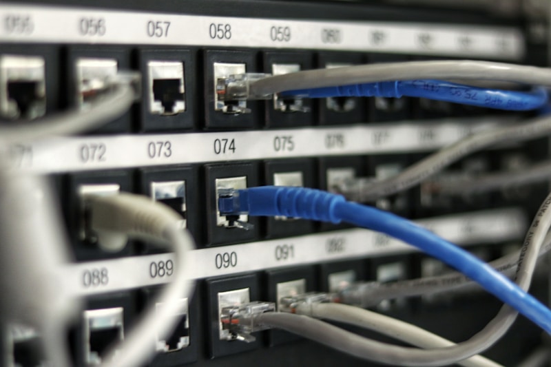
Structured cabling installed during fit-out costs a fraction of retrofitting the same pathways after walls and ceilings close
1. Why Structured Cabling Is the Backbone of Office Networks
Every technology an enterprise depends on — VoIP telephony, cloud applications, video conferencing, Wi-Fi, IP security cameras, smart building sensors — ultimately rides on the same physical layer of copper and fiber. Structured cabling is the standardized framework that organizes that physical layer into predictable, testable, and documented subsystems. When it is done right, nobody notices it. When it is done wrong, the symptoms surface for a decade: intermittent drops, ports that pass link but fail under load, and closet "archaeology" every time a technician traces a connection.
The economics explain why the market keeps expanding. According to Global Market Insights, the global structured cabling market was valued at $20 billion in 2025 and is forecast to reach $44.5 billion by 2035, growing at 8.4 percent CAGR. North America holds a 38.2 percent revenue share, led by data center expansion, smart building deployments, and the modernization of legacy office infrastructure. CommScope alone commands over 29 percent of the market, and the top five vendors — CommScope, Corning, TE Connectivity, Panduit, and Legrand — collectively hold 52.1 percent, a concentration that reflects how much enterprises value certified end-to-end systems.
Within that market, copper still carries the majority of office connections at roughly 50 percent of product revenue, while the LAN segment accounts for over 82 percent of application revenue. But the composition is shifting: fiber adoption in new builds continues climbing as backbone demands grow, and Power over Ethernet is pulling more device categories onto the structured cabling plant than ever before. For a fuller treatment of the concept itself, see our companion article on what structured cabling means for SMB and campus networks.
2. Structured vs Point-to-Point Wiring: The Real Cost Difference
Before structured cabling became the norm, offices were wired point-to-point: a single cable run from each device directly to wherever its destination happened to be. Every new device meant a new custom run, and every reconfiguration meant abandoning the old cable in the ceiling and pulling another. The result was the infamous "cable spaghetti" that still plagues legacy closets today — unlabeled, undocumented, and effectively unfixable.
Structured cabling replaces that chaos with a hub-and-spoke model. All horizontal cables terminate on patch panels in telecommunications rooms, and all services — data, voice, cameras, access points — connect through short, managed patch cords at a main distribution area (MDA). Moving a user from one VLAN to another becomes a two-minute patch cord change instead of a cable pull. This is the essence of a structured system: the fixed infrastructure never changes, and all flexibility happens at the patch layer.
The business case shows up in three places on the balance sheet:
- Maintenance labor: organized, labeled cabling cuts mean-time-to-repair dramatically because technicians trace faults by label instead of by tone generator.
- Moves, adds, and changes (MACs): the average office churns 25 to 40 percent of its workforce annually. Structured systems absorb that churn at patch-cord cost.
- Downtime avoidance: a cabling fault in an unstructured plant can take hours to isolate; the same fault in a structured, certified plant is usually isolated in minutes.

The difference between point-to-point wiring and structured cabling is the difference between archaeology and administration
3. The Six Subsystems of Structured Cabling
Both ANSI/TIA-568 and ISO/IEC 11801 divide a building's cabling into six standardized subsystems. Understanding them is essential because every design decision, budget line, and test record maps back to one of these six buckets.
| Subsystem | Function | Typical Location |
|---|---|---|
| Entrance Facilities | Where the building cabling meets the service provider's network; includes demarcation point and surge protection | Building perimeter, often adjacent to the main equipment room |
| Equipment Room | Houses the core network: campus switches, routers, firewalls, servers, and the MDA | Central, environmentally controlled space |
| Backbone Cabling | Connects the equipment room to each telecommunications room, typically fiber plus Cat6a for interconnect | Building risers and inter-building conduit |
| Telecommunications Rooms (TR/IDF) | Floor-level hubs where horizontal cables terminate on patch panels and connect to access switches | One per floor or per 1,000 sq meters, within 90m of all outlets |
| Horizontal Cabling | The fixed 90-meter runs from TR patch panels to work area outlets | Above ceilings, in conduit, or under raised floors |
| Work Area Components | Outlets, faceplates, and equipment patch cords connecting end-user devices | Desks, walls, ceilings (APs), building perimeter (cameras) |
The main distribution area (MDA) sits at the center of this architecture. Because every backbone and horizontal element converges there, the MDA is where cross-connects, interconnects, and all major service distribution happen. A well-designed MDA lets you re-patch any port in the building to any service without touching the fixed cabling. For a deeper treatment of how these interconnection patterns differ, see our guide to interconnect vs cross-connect vs EOR patch panel topology.
Some modern designs add consolidation points (CPs) — interconnection boxes in the ceiling or under raised floors that allow a single horizontal run to fan out to multiple nearby outlets. CPs are permitted by the standards, but they must never be daisy-chained, and each CP-to-outlet run must remain within the 90-meter permanent link budget.
4. Standards That Govern Every Installation
Structured cabling is one of the few IT disciplines where the rulebook is genuinely international, mature, and enforceable. Four standard families cover virtually every office project:
4.1 ANSI/TIA-568 Series
The foundation of North American structured cabling, defining cable categories from Cat5e through Cat8, the T568A/T568B pin assignments, the 90-meter permanent link plus 10-meter patch cord channel model, and the field test requirements for each category. TR-42 is currently consolidating ANSI/TIA-568.0, 568.1, and 862 into a single document, ANSI/TIA-568.1-F, which went to ballot and public review in 2026. The consolidation folds building automation system cabling into the main premises standard — a formal acknowledgment that HVAC sensors, access control, and lighting now share the same infrastructure as data.
4.2 ISO/IEC 11801
The international counterpart used across Europe, Asia, and the Middle East. The current edition is ISO/IEC 11801-1:2017 with its 2025 amendment, and it uses Class nomenclature rather than Category: Class EA corresponds to Cat6a, Class F/FA to Cat7/Cat7A (which TIA never adopted), and Class I/II to Cat8. The critical procurement trap: a spec calling for "Class F" without naming the connector system allows a contractor to install GG45 or TERA connectors incompatible with your existing RJ45 patch cords. For a side-by-side breakdown, read our structured cabling standards comparison: TIA-568 vs ISO/IEC 11801.
4.3 Supporting TIA Standards
- TIA-606-C: labeling and administration — the standard behind every cable label, port identifier, and color code scheme.
- TIA-569: pathways and spaces — conduit sizing, tray fill ratios, and telecommunications room dimensions.
- TIA-607: grounding and bonding for telecommunications systems, mandatory for shielded systems and rack grounding.
- TIA-942: data center-specific cabling, relevant when your office project includes an on-prem server room. Our coverage of TIA-942-C compliance changes explains what changed.
4.4 BICSI and Installer Credentials
BICSI's RCDD (Registered Communications Distribution Designer) certification is the recognized credential for structured cabling design, and Installer 2 for copper and fiber installation. Most manufacturer warranty programs — the 25-year performance warranties from CommScope, Panduit, Legrand, and peers — are void unless a registered installer performs and documents the work.
5. Cable Media: Cat6a Copper and Fiber Backbone
Media selection follows a simple rule: copper to the desk, fiber between rooms. The horizontal layer uses balanced twisted-pair copper for its PoE capability and device compatibility, while the backbone uses fiber for its distance, bandwidth, and EMI immunity. Here is how the copper categories compare for office use:
| Category | Bandwidth | Max Speed / Distance | PoE Readiness | Verdict for 2026 Offices |
|---|---|---|---|---|
| Cat5e | 100 MHz | 1G / 100m | PoE+ adequate, PoE++ marginal in bundles | Legacy only — retain healthy runs, never install new |
| Cat6 | 250 MHz | 10G / 37-55m | PoE++ workable, watch bundling heat | Retrofit use where 10G is not planned |
| Cat6a | 500 MHz | 10G / 100m | PoE++ 90W with thermal headroom | The new-build office default |
| Cat8 | 2000 MHz | 25/40G / 30m | Data center focused | Top-of-rack only, not horizontal cabling |
Cat6 remains the highest-volume installed category — segment research puts its share near 52.8 percent of cable-type revenue through 2026 — but that reflects the enormous installed base, not the direction of new builds. In North America, Cat6a is now the baseline specification for new commercial construction because it delivers 10GBASE-T to the full 100-meter channel, handles 90W PoE++ (802.3bt Type 4) without the thermal derating that smaller conductors suffer, and controls alien crosstalk in bundled trays. For help matching category to a specific application mix, see our guide on how to precisely choose cable category based on network needs and the broader Cat6 vs Cat6a vs Cat7 vs Cat8 comparison for SMB upgrades.
For the backbone, the choice is between multimode (OM4/OM5) and singlemode (OS2). Multimode remains cost-effective for intra-building runs up to 400-550 meters at 10-100G using VCSEL optics; singlemode future-proofs for 400G and beyond at slightly higher transceiver cost. Most new office builds run both: OM4 for floor-to-floor risers, OS2 for campus links and anything longer. Our singlemode vs multimode selection guide and the OS2 and OM1-OM5 fiber types explained article cover the full decision tree.

A well-organized telecommunications room: copper patch panels below, fiber backbone panel above, every port labeled to TIA-606-C
6. Designing the Office Floor: MDF, IDF, and Horizontal Cabling
Floor design is a geometry problem governed by the 90-meter rule. Every work area outlet must sit within 90 meters of horizontal cable from its serving telecommunications room, measured along the actual pathway — not as the crow flies. In practice this means one TR (also called an IDF) per floor for most buildings, or one per 1,000 to 1,200 square meters of open floor plate, with all TRs homed back to the main equipment room (MDF) over fiber backbone.
Standard density planning for a 2026 office looks like this:
- Desks: two Cat6a outlets per workstation position — one for the computer/dock, one for phone or a second device
- Ceiling: one to two Cat6a drops per Wi-Fi access point location, PoE-fed, spaced roughly one AP per 100-120 square meters for Wi-Fi 6E/7 coverage
- Perimeter: Cat6a to every camera position and door access control point
- Spare: 30 percent spare outlets and pathway capacity minimum, because adding a conduit after the ceiling closes costs ten times more than installing it during fit-out
On the head end, decide early between 24-port and 48-port patch panels. Higher density saves rack space but concentrates cable bundles; our 24-port vs 48-port patch panel density analysis covers the trade-offs. Pair panels with proper horizontal cable management — the difference between a rack you can re-patch in minutes and one you fear is usually just 1U cable management done properly.
For tight construction schedules, pre-terminated copper trunks can cut field termination labor by half and come factory-tested with certification reports. The trade-off is exact pathway measurement discipline — pre-terms leave no margin for measurement error. Our installation team's notes on how pre-terminated cabling accelerates delivery cover when the premium pays back.
- Every outlet within 90m of its serving TR, verified against actual pathway routing
- TR locations confirmed with power, cooling, and grounding provisions coordinated
- Backbone fiber counts sized for 2x current need plus spare pairs per pathway
- Two-outlet standard per desk, Cat6a minimum, verified non-CCA 100 percent copper
- 30 percent spare capacity in outlets, tray fill, and panel ports
- Labeling schema defined per TIA-606-C before the first cable is pulled
7. PoE, Wi-Fi 7, and Smart Building Readiness
Three converging trends are quietly transforming office cabling loads, and all three land on the horizontal copper plant simultaneously.
Power over Ethernet. With 802.3bt Type 4 delivering up to 90 watts per port, the structured cabling system has become the building's low-voltage power grid: Wi-Fi 7 access points, PTZ cameras, video wall displays, smart lighting ballasts, and even desktop monitors now draw power from the same Cat6a that carries their data. This changes the engineering calculus. Bundled cables carrying 90W dissipate heat — a 24-cable bundle can rise 15 degrees Celsius above ambient — so cable gauge, bundle size, and pathway ventilation all become design inputs. Our 802.3bt cabling guide on gauge, length, and bundling heat and the 23AWG vs 24AWG comparison for PoE runs quantify the limits, and the complete PoE standards glossary covers the 802.3af/at/bt landscape.
Wi-Fi 7 and Multi-Gig. A Wi-Fi 7 enterprise access point can consume 2.5G to 10G of uplink bandwidth plus 30-60W of power — demands that only a Cat6a drop satisfies simultaneously. Existing Cat5e and Cat6 plants can carry 2.5GBASE-T under TSB-5021 conditions, but real-world limits bite quickly in bundled installations; see our field data on 2.5G/5G over Cat5e and Cat6 and the design patterns for PoE cabling to cameras and Wi-Fi APs.
Smart building convergence. GSMA Intelligence forecasts over 38 billion IoT connections by 2030, and a large share of those devices live in commercial buildings: occupancy sensors, air quality monitors, intelligent lighting, access control. The 568.1-F consolidation folds building automation cabling into the main standard precisely because BAS traffic now shares pathways, panels, and patching with the data network. Designing the cabling plant as a single converged infrastructure — rather than parallel systems for IT, security, and facilities — is no longer optional for new builds.
8. Installation Best Practices That Prevent Certification Failures
Industry data consistently shows first-pass certification yields of 93 to 97 percent even for professional installers. The three to seven percent of failed links almost always trace back to a handful of installation sins — all avoidable.
- Bend radius: never bend copper tighter than four times its outside diameter, or fiber tighter than ten times. A single kink produces return loss failures that only surface at high frequencies.
- Power separation: maintain at least 50mm (2 inches) between data cables and parallel power runs; cross power at 90 degrees when unavoidable. Unshielded bundles drifting alongside 480V feeds will fail alien crosstalk margins intermittently.
- Untwist discipline: keep pair untwist at termination under 13mm for Cat6a — the single most common cause of NEXT failures.
- Zip tie tension: snug, never crushed. Over-cinched bundles deform pair geometry and create distance-dependent crosstalk faults.
- Pulling tension: respect the 110N (25 lbf) maximum for 4-pair Cat6a and use lubricant in conduit. Leave service loops at both ends.
- Fire-stopping: every penetration of a fire-rated wall or floor must be sealed with rated intumescent material and photographed for the handover package.
Material quality matters as much as technique. Counterfeit and copper-clad aluminum (CCA) cable remains endemic in low-bid projects — it fails PoE at distance, overheats in bundles, and voids warranties. Our CCA vs solid copper risk analysis shows the failure mechanisms. Jacket selection follows the building code: plenum (CMP/OFNP) for air-handling spaces, riser (CMR/OFNR) for vertical shafts, and LSZH for occupied spaces where halogen smoke is the hazard — our cable jacket materials guide decodes the ratings and the PVC vs LSZH comparison covers the environmental decision.
At the work area end, termination quality decides whether the 90 meters of perfectly pulled cable actually passes. Follow our step-by-step keystone jack termination guide at the outlet and the Cat6/Cat6a patch panel punch-down procedure at the head end.

Every installed link must pass field certification with positive margin — no certificate, no warranty, no acceptance
9. Testing, Certification, and Documentation
Testing is not a phase; it is the acceptance criteria. Every copper link must be certified to its category's limits using a Level 2G/VI field certifier — the Fluke DSX-8000 or DSX-5000 class of instrument — measuring wire map, length, insertion loss, NEXT, PSNEXT, return loss, ACR-F, and propagation delay. Fiber links require Tier 1 optical loss testing (and OTDR Tier 2 for backbone), plus end-face inspection before every connection is made.
Understand the two test configurations before you write the RFP. Permanent link testing certifies the fixed infrastructure from panel to outlet, excluding patch cords — the standard for new installations because it isolates the contractor's workmanship. Channel testing adds the patch cords at both ends and reflects what the connected equipment actually experiences. The distinction matters for acceptance, warranties, and troubleshooting; see our permanent link vs channel testing guide, including the newer MPTL (modular plug terminated link) standard for camera and AP drops that terminate directly on a plug, plus the component vs channel testing comparison.
Documentation is what converts a one-time certification into a 25-year asset:
- Labeling per TIA-606-C at both ends of every cable, every panel port, and every outlet — machine-printed, never handwritten.
- As-built drawings showing actual outlet locations, pathway routing, and TR equipment layouts.
- Certification reports — one per link, digitally stored, with tester model, serial number, calibration date, and pass margins. Retain for the warranty period; 15 years is the common baseline. Learn to read them critically with our guide on how to read Fluke test reports for procurement.
- A patching database mapping every outlet to its panel port and VLAN, updated with every MAC.
The final brick is the manufacturer's system warranty. Tier-one vendors extend 25-year application assurance warranties covering components and channel performance — but only when all components come from a single certified system, installed by a registered installer, and documented with certification reports. That warranty registration certificate belongs in the building's O&M manual alongside the test data. For advice on vetting partners, see our B2B guide to choosing a network cabling supplier.
10. Common Mistakes and the Business Case for Doing It Right
After thousands of office installations, the same failure patterns recur. Each one is cheap to avoid during design and expensive to fix after occupancy:
| Mistake | Consequence | Prevention |
|---|---|---|
| Under-counting outlets to save budget | Drilling into finished walls in year one | Two outlets per desk + 30 percent spare |
| TR placed beyond 90m of farthest outlet | Permanent links cannot pass; zone extenders needed | Verify pathway distances during design, not after pull |
| Mixing component categories in one channel | Entire channel derates to lowest component | Match cable, jack, panel, and patch cord categories end-to-end |
| Bargain patch cords | Certified links fail at the last meter; intermittent errors | Specify ETL-verified cords; treat cords as part of the channel |
| Daisy-chained consolidation points | Violates one-link rule; troubleshooting becomes guesswork | One CP per horizontal run, never cascaded |
| No as-built documentation | Every future change becomes cable archaeology | TIA-606-C labeling plus digital as-builts at handover |
| Skipping independent certification | Faults surface after fit-out; warranty void | No certificate, no acceptance, no final payment |
The business case compresses to one comparison: Cat6a over Cat6 adds 10 to 15 percent to material cost in a new build, while a rip-and-replace project after occupancy costs three to five times the original cabling budget — and that is before counting business disruption. Cabling is roughly 3 to 5 percent of a commercial fit-out budget, yet it determines the performance ceiling of every system above it. Approached that way, over-specifying the physical layer is the cheapest insurance in the building. Our analysis of network cable total cost of ownership and the cable procurement strategy hub provide the framework for building that case for your CFO.
Key Questions
Q1: What is structured cabling?
Structured cabling is a standardized approach to designing and installing a building's telecommunications infrastructure using six defined subsystems: entrance facilities, equipment room, backbone cabling, telecommunications rooms, horizontal cabling, and work area components. Unlike point-to-point wiring, it uses patch panels and a main distribution area so any device can connect to any service through documented, testable pathways supporting voice, data, video, and PoE.
Q2: How long does a structured cabling system last?
A properly installed and certified system should serve a building for 15 to 25 years — typically three to four generations of active equipment. Most tier-one manufacturers offer 25-year performance warranties when certified components are installed by registered installers. Cabling outlives switches because the standards are designed with headroom for future applications.
Q3: Is Cat6a worth the extra cost over Cat6 for a new office?
For new construction, yes. Cat6a adds roughly 10 to 15 percent to material cost and less to labor, while delivering 10GBASE-T to the full 100-meter channel, 90W PoE++ thermal headroom, and alien crosstalk immunity. A future rip-and-replace costs three to five times the original cabling budget once walls and ceilings are closed.
Q4: What is the 90-meter rule in structured cabling?
ANSI/TIA-568 limits the permanent link — the fixed cabling from patch panel to wall outlet — to 90 meters, with up to 10 meters of patch cords across both ends for a maximum 100-meter channel. This is why telecommunications room placement during design is critical: every outlet must fall within 90 meters of its serving TR along the actual cable pathway.
Q5: Should my project follow TIA or ISO/IEC 11801 standards?
North American deployments are governed primarily by ANSI/TIA-568; international projects more commonly reference ISO/IEC 11801. Performance specifications are closely harmonized, but ISO uses Class designations (Class EA equals Cat6a) and recognizes Cat7/Cat7A with GG45 or TERA connectors that TIA never adopted. Multinational organizations should specify both standards and require dual test reporting.
Q6: How much spare capacity should I plan for?
Design for at least 30 percent spare capacity in outlets, pathways, and patch panel ports. Spare pathway installed during construction costs a fraction of retrofitting it later. Capacity planning should also cover ceiling drops for future Wi-Fi access points, cameras, and IoT sensors, not just desk positions.
Q7: What is the difference between permanent link and channel testing?
Permanent link testing certifies only the fixed infrastructure — patch panel to wall outlet, excluding patch cords — and is the standard method for new-installation certification. Channel testing measures the complete end-to-end connection including patch cords at both ends. Cat6a installations must also account for alien crosstalk between bundled cables, which can require additional sampling in large bundles.
Q8: When should existing office cabling be upgraded or re-certified?
Re-certify after every move, add, or change, and audit the full plant every three years. Upgrade triggers include VoIP or cloud migrations, Wi-Fi 6E/7 rollouts, and Multi-Gig switch upgrades. Healthy Cat5e carrying 1G to the desk can remain in service, but any new installation should be Cat6a minimum.
About AMPCOM
AMPCOM is a leading manufacturer of structured cabling products for enterprise and data center networks, including network cables, patch cables, patch panels. Our products undergo rigorous testing to meet TIA-568, ISO/IEC 11801, and IEEE 802.3 standards, and we provide full certification documentation for enterprise warranty registration.
Related Articles
- What Is Structured Cabling for SMB and Campus Networks? — Foundational companion to this guide, explaining the core concepts of structured cabling for smaller deployments: subsystem roles, patch panel architecture, and how the MDA model scales down to single-closet offices
- Structured Cabling Standards: TIA-568 vs ISO/IEC 11801 — Side-by-side technical comparison of the two dominant standards families, covering category vs class nomenclature, connector systems, and how to specify compliance for international projects
- Complete Blueprint for the Next-Generation Office Network — Holistic design guide that extends structured cabling into switching, Wi-Fi, and services layers for a zero-friction office network build
- Permanent Link vs Channel Testing (Including MPTL) — Deep dive into field certification configurations: what each test measures, when to require each type in an RFP, and how the MPTL standard handles camera and AP drops terminated on plugs

AMPCOM Technical Team
Industry experts with 17+ years in structured cabling design, office network infrastructure, and TIA/ISO certification standards
Planning an office cabling project?
Our technical team provides free consultation on structured cabling design, Cat6a and fiber media selection, TIA-568 compliance, and complete office network cabling solutions backed by certified test documentation.
Get Free Expert Consultation

