
Data Center Structured Cabling: Complete Design Guide
Published:Executive Summary: Structured cabling is the nervous system of any data center — poorly designed, and every upgrade becomes a construction project; well-designed, and it becomes a competitive advantage. This guide covers the complete design framework from TIA-942-C topology to cable selection, redundancy tiers, and AI-ready infrastructure planning.
Whether you're building a new facility or modernizing an existing one, this 2026 design guide gives you the architecture, standards compliance checklist, and real-world implementation insights to build a data center that won't need a forklift upgrade in three years.
Quick Navigation
- 1 What Is Data Center Structured Cabling?
- 2 TIA-942-C Space Hierarchy: MDA, HDA, EDA Topology
- 3 TIA-942 Rated Tiers and Redundancy Requirements
- 4 Cable Selection: Fiber and Copper for Each Layer
- 5 Design Best Practices for Scalability
- 6 TIA-942-C Key Updates for 2026
- 7 Common Design Mistakes to Avoid
- 8 Frequently Asked Questions

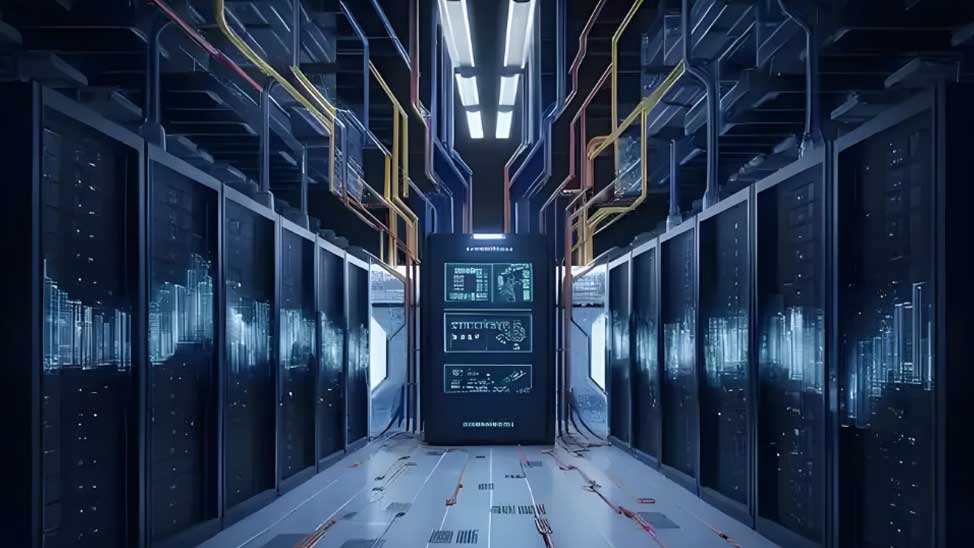
A well-designed structured cabling system enables predictable airflow, fast troubleshooting, and painless capacity additions — the foundation of any operationally excellent data center
1. What Is Data Center Structured Cabling?
Data center structured cabling is a standardized, hierarchical approach to organizing network cables and connectivity points within a data center facility. Unlike point-to-point (unstructured) wiring — where each device connects directly to another with a dedicated cable run — structured cabling centralizes fixed plant in designated distribution areas, enabling any change to be made by swapping a patch cord rather than re-routing a permanent run.
The contrast between these two approaches becomes stark over the plant lifecycle. Structured cabling costs more upfront but pays back over 5+ years through faster troubleshooting and fewer re-cabling projects. Point-to-point deployments look cheaper on day one but accumulate operational debt — as documented in common real-world data center cabling pitfalls, facilities that optimized for initial cost consistently face 3–5x higher total cost of ownership by year five.
1.1 The Five Functional Areas
Per TIA-942-C (released April 2024), every data center structured cabling system is built around five functional spaces: MDA, IDA, HDA, ZDA, and EDA. Every facility requires at least one MDA and one HDA; IDA and ZDA are optional depending on size and topology. Understanding how these areas interconnect is foundational — for a broader view of how TIA standards work alongside TIA-942, see our guide comparing TIA-568 and ISO/IEC 11801 structured cabling standards.
2. TIA-942-C Space Hierarchy: MDA, HDA, EDA Topology
The TIA-942 standard organizes data center cabling around five functional spaces, each serving a specific role in the connectivity hierarchy. Understanding this topology is prerequisite to any design decision.
2.1 Entrance Room (ER)
The Entrance Room (ER) is the interface between the data center's structured cabling and external networks — access provider connections, carrier demarcation points, and inter-building backbone cables. The ER may be located inside or outside the computer room. For security reasons, many modern data centers place the ER outside the secure computer room, so access provider technicians never enter the white space.
2.2 Main Distribution Area (MDA)
The Main Distribution Area (MDA) is the central hub of the data center's cabling infrastructure. Every data center requires at least one MDA. It houses the main cross-connect (MC) and typically the core routers, core LAN switches, core SAN switches, and sometimes PBX systems.
The MDA serves as the central distribution point for all backbone cabling — connecting to IDA (if present), HDA(s), and any telecommunications rooms outside the computer room. In colocation facilities, the MDA is often in the meet-me-room, allowing tenants to cross-connect without entering the white space.
2.3–2.6 Intermediate, Horizontal, Zone, and Equipment Distribution Areas
The Intermediate Distribution Area (IDA) is an optional aggregation tier for large data centers where a single MDA cannot efficiently reach every HDA. The Horizontal Distribution Area (HDA) is the transition point between backbone and horizontal cabling, housing the horizontal cross-connect and typically LAN/SAN aggregation switches. Most data centers have one HDA per row or zone — in top-of-rack (ToR) architectures, the HDA may be eliminated entirely because access switches reside in the same cabinet as the servers.
The Zone Distribution Area (ZDA) is an optional reconfiguration point within the horizontal run — it must not contain cross-connects or active equipment. The Equipment Distribution Area (EDA) is where horizontal cabling terminates at patch panels and connects to servers and storage in racks — and it's the most densely cabled space in the facility. Maintaining proper cable management in the EDA is critical; facilities that neglect this area consistently rank it as their top operational pain point, as covered in our patch panel cable management guide for data centers.
TIA-942-C defines a hierarchical cabling topology: signal flows from ER → MDA → (IDA →) HDA → (ZDA →) EDA, with backbone cabling between distribution areas and horizontal cabling to server cabinets
3. TIA-942 Rated Tiers and Redundancy Requirements
TIA-942 defines four reliability ratings that govern physical construction, power, cooling, monitoring, and — critically for our purposes — cabling redundancy. Each tier builds on the one below it, and the defining differentiator is the cabling pathway model.
| TIA-942 Rating | Name | Cabling Pathways | Redundancy | Target Uptime | Typical Use Case |
|---|---|---|---|---|---|
| Rated 1 | Basic | Single, non-redundant | None | 99.671% | Small businesses, non-critical workloads |
| Rated 2 | Redundant Capacity | Single pathway | N+1 components | 99.741% | Medium enterprises, development/test environments |
| Rated 3 | Concurrently Maintainable | Dual, independent pathways | N+1 system | 99.982% | Mission-critical applications, colocation |
| Rated 4 | Fault Tolerant | Dual, active pathways | 2N or 2N+1 | 99.995% | High-availability, financial, healthcare |
3.1 The Rated 3 vs. Rated 4 Cabling Requirement
The jump from Rated 2 to Rated 3 is where the cabling design fundamentally changes. Rated 3 and 4 require dual physically separated cabling pathways — not just separate ports on the same switch, but cables that travel through separate conduits and separate cable trays. This is a common compliance gap discovered during certification audits — not during design review. One frequently overlooked pitfall is routing redundant paths through a shared tray "for simplicity"; this satisfies nothing in the eyes of a Rated 3 auditor.
4. Cable Selection: Fiber and Copper for Each Layer
Each functional area in the TIA-942 topology has specific cable media requirements. Choosing the wrong media — or the wrong grade within a media type — creates bottlenecks that cascade through the entire infrastructure.
4.1 Backbone Cabling (MDA ↔ HDA ↔ IDA)
Backbone cabling connects distribution areas across the facility. For modern data centers, fiber is the dominant backbone medium — and for good reason. A comprehensive comparison of the different types of fiber optic cables available today shows why singlemode OS2 and laser-optimized multimode OM4 dominate backbone designs: they offer fundamentally different distance and bandwidth envelopes that match the actual topology of enterprise and hyperscale facilities.
For new backbone installations, OS2 singlemode fiber is the clear choice. It supports 400G and beyond over any distance a data center can physically span, with ≤ 0.35 dB/km attenuation at 1310nm and ITU-T G.652.D compliance. OM4 multimode remains acceptable for cost-sensitive builds where all runs stay under 300m, but it limits the upgrade path to 100G — a constraint that becomes expensive within 3–5 years as AI workloads push speeds higher.
Beyond fiber type, the connector interface matters enormously. MPO trunk cables (12F or 24F) — pre-terminated assemblies that arrive factory-tested — deliver consistent insertion loss performance and dramatically faster installation than field termination. When selecting MPO polarity for a new MPO deployment, the choice between Type A, B, and C polarity configurations has significant implications for link reliability; our MPO polarity types guide covers the tradeoffs in detail.
Backbone Cabling Quick Reference
- Rated 3/4 facilities: Dual redundant fiber paths — route each through physically separate trays and conduits
- Fiber count sizing: Plan for 2× current demand plus 30% growth headroom as a minimum. Common problems in fiber optic installation — undersized counts, bend violations, contamination — almost always trace back to day-one underplanning
- Connector standard: TIA-568.3 compliant throughout; LC required at equipment outlets per TIA-942-C, any 568.3-compliant connector acceptable in distribution areas
- Pre-terminated vs. field-terminated: MPO pre-terminated saves 60–80% on installation labor. For custom-length runs or critical paths where connector quality is paramount, fusion splicing with fiber optic pigtails delivers lower insertion loss than any field-terminated connector
4.2 Horizontal Cabling (HDA ↔ EDA)
Horizontal cabling runs from the HDA to server racks in the EDA. The dominant pattern in 2026 data centers is a hybrid approach: copper at the access layer, fiber for aggregation and backbone. But this balance is shifting — AI infrastructure demands are pushing fiber deeper into the EDA than traditional designs ever required. Our AI infrastructure cabling requirements analysis documents how GPU cluster deployments have fundamentally changed the speed and density expectations for the access layer.
| Application | Recommended Media | Notes |
|---|---|---|
| Server-to-switch (≤100m) | Cat6A S/FTP or Cat8 | Cost-effective for 10G/25G, full PoE++ support |
| High-speed server links (100G+) | OM4 multimode or OS2 singlemode | DAC/AOC for same-rack; structured fiber for cross-rack |
| ToR switch uplink to HDA | OS2 singlemode or OM4 | MPO trunk for 400G+; LC duplex for 10G/25G |
| Storage area network (SAN) | OM4 or OS2 | 32G/64G FC or NVMe-of fabric; match media to distance |
4.3 TIA-942-C Cabling Updates: What Changed in 2024
TIA-942-C introduced several changes that reshape new designs:
- Single-pair balanced twisted-pair cable — now a recognized horizontal medium for IoT and control applications (SP1-400: 400m max, 5 connections; SP1-1000: 1000m max, 10 connections)
- Any TIA-568.3 compliant connector — permitted in all distributor areas; LC and MPO still required only at the equipment outlet (EO)
- Minimum 2 optical fibers — recommended for all horizontal and backbone runs (single-fiber deployments are no longer standard practice)
- 800mm minimum cabinet width — mandatory in MDA, HDA, and IDA — the 600mm cabinets still common in older facilities cannot accommodate the cable densities required for 400G/800G networks
5. Design Best Practices for Scalability
A data center designed for today's requirements that ignores tomorrow's growth is a liability. These principles separate a 10-year infrastructure from a 3-year one.
5.1 Plan the Growth Horizon First
Define a 3–7 year capacity and speed horizon before finalizing media choices and pathway sizes. The fiber plant is inexpensive per meter; the cost of pulling new cable through a congested pathway later is not. This is especially true in 2026: 800G and 1.6T data center cabling trends show that 400G is already the baseline speed for AI workloads, meaning facilities built for 10G/25G in 2023 are facing immediate retrofit pressure.
The 40% Pathway Fill Rule
Never exceed 40% fill ratio in any cable tray or conduit at commissioning. A data hall designed at maximum capacity on day one will hit 70%+ within 18 months — blocking future pulls, obstructing airflow, and recreating the spaghetti conditions structured cabling was designed to eliminate. The cost of specifying larger cable trays is trivial compared to the cost of re-engineering a congested pathway system. Proper data center cable management practices are what keep a facility from degrading to this state over time.
5.2 MPO Infrastructure for AI-Ready Capacity
AI workloads are driving unprecedented fiber counts. TIA-942-C commentary notes: "400G is the base speed for AI. In 2026, we'll have 1.6 Terabit, which uses 16 fibers. Designers are working on connections between AI clusters requiring 70,000–80,000 fibers between rooms." For any facility planning beyond 2026:
- Deploy MPO-24 trunk infrastructure from day one, even if current speeds only need 12 fibers — the marginal cost is negligible compared to retrofitting later
- Consider VSFF (very small form factor) connectors — MDC, SN, and CS — to achieve extreme port densities in HDA and MDA cabinets. 288-fiber high-density solutions demonstrate the capacity available with current connector technology
- Run OS2 singlemode as backbone even for short distances — the fiber cost is marginal compared to the cost of pathway reconstruction when speeds inevitably increase
- Use bend-insensitive fiber (OM4-BI or OS2-BI) throughout — tight-radius routing inside cabinets is unavoidable at modern densities, and non-BI fiber accumulates silent attenuation losses that degrade BER without triggering obvious failures
5.3 Structured Cabling vs. Direct Attach: Where Each Belongs
TIA-942 states that direct-attach cabling (DAC/AOC) should only be used between equipment in the same cabinet or adjacent cabinets. Beyond a single row, structured cabling becomes mandatory:
- Same cabinet: DAC/AOC is fine — shortest distance, lowest cost
- Adjacent cabinet (same row): DAC acceptable for AI pod connections where GPU nodes connect to leaf switches
- Beyond one row: Structured cabling is mandatory — tray capacity for hundreds of DAC cables becomes unmanageable, and airflow suffers significantly
- Cross-hall or cross-building: Structured fiber is the only viable solution
5.4 Cable Management Ratios and Material Choices
The industry best practice is 1:1 horizontal cable management per 1U of active equipment — for every 1U of switches, allocate 1U of cable management. For high-density MPO environments, increase to 1.5U of management per 1U of equipment to accommodate the larger bend radius of MPO trunks. See our complete patch panel cable management guide for the full ratio framework and implementation steps.
For cable attachment material, use Velcro (hook-and-loop) straps for all accessible areas — they distribute pressure evenly, can be released and re-secured in seconds, and outperform zip ties in long-term jacket integrity. Reserve zip ties only for permanent, inaccessible bundles inside sealed conduits.
6. TIA-942-C Key Updates for 2026 and Beyond
TIA-942-C (May 2024) is the most significant revision in a decade. Beyond cabling changes, it reshapes sustainability expectations, thermal management standards, and introduces the first formal treatment of edge data centers.
6.1 Sustainability and Climate Adaptation
The standard adds requirements for site selection risk analysis, self-generated power (renewables, hydrogen fuel cells, BESS), and energy-efficient infrastructure design. For cabling designers, this means planning cable pathways to accommodate future power infrastructure additions without disrupting white space — and recognizing that organized cabling directly reduces HVAC energy consumption by 5–15% through improved airflow.
6.2 Thermal Management and Liquid Immersion Cooling
TIA-942-C aligns with ASHRAE TC 9.9's 5th edition and introduces a new H1 thermal class (18–22°C, stricter than the previous A1 class at 18–27°C). For liquid immersion cooling deployments, the standard now includes an informative annex; cable materials — including fiber connectors, copper jackets, and structured cabling components — must be evaluated for compatibility with dielectric cooling fluids.
6.3 Edge Data Centers
TIA-942-B-1 (edge data centers) is now incorporated into TIA-942-C. Edge deployments assume minimal on-site technical staff, making pre-terminated solutions strongly preferred for faster deployment and lower skilled-labor requirements. Plan for remote management and monitoring of the entire cabling infrastructure from day one.
7. Common Design Mistakes to Avoid
Top 7 Data Center Cabling Design Mistakes
Mistake #1: Undersized cabinets
Using 600mm cabinets in HDA/MDA areas when TIA-942-C mandates 800mm minimum. At 600mm width, cable management becomes physically impossible at the densities required for 400G/800G networks. Bend radius violations become common, and airflow degrades as cables fill available space. The retrofit cost of replacing 100 cabinets is orders of magnitude higher than specifying 800mm from day one.
Mistake #2: Exceeding 40% pathway fill at commissioning
Designing pathways for maximum initial capacity creates immediate congestion as the facility begins growing. Facilities documented in real-world data center cabling pitfall analyses consistently show that the worst operational chaos occurs in facilities optimized for day-one cost at the expense of pathway capacity.
Mistake #3: Single-pathway design for Rated 3 requirements
A shared cable tray for both primary and redundant cabling does not satisfy Rated 3 requirements. Each redundant path must travel through physically separate conduits and trays. This is discovered during certification audits — after the facility is built.
Mistake #4: Choosing multimode for backbone runs that exceed 300m
OM3 and OM4 are excellent for horizontal cabling, but using them for backbone runs beyond their effective range creates bottlenecks that appear years after deployment. Choosing the right fiber optic cable supplier means selecting OS2 singlemode for backbone — the per-meter cost premium is marginal, and it supports every speed from 1G to 800G+ without cable replacement.
Mistake #5: Skipping pre-terminated infrastructure planning
MPO trunk systems deliver 60–80% labor savings on installation and come factory-tested for insertion loss performance. Even in facilities that will field-terminate some custom runs, fusion splicing with pigtails should be planned for backbone and high-count connections where connector quality is paramount.
Mistake #6: Ignoring connector polish type consistency
Mixing APC and UPC connectors in a fiber link causes ≥ 20 dB return loss — creating a reflective surface that degrades BER. Always specify the same polish type throughout a link. Use APC for DWDM systems and high-return-loss requirements; UPC for general data center applications.
Mistake #7: No labeling or documentation until project closeout
As-built documentation must reflect the installed plant — not the design intent — and must be delivered in both PDF and editable format at project closeout. Every cable needs a unique identifier at both ends. Machine-printed labels are mandatory per TIA-606-C; handwritten labels fail compliance and create liability during audits. Our cable color coding and labeling best practices guide provides a ready-to-implement system.
8. Frequently Asked Questions
This section addresses the most common questions from data center designers and operators working through TIA-942-C compliance, cable selection, and capacity planning decisions.
Frequently Asked Questions About Data Center Structured Cabling
Related Articles
- What Are the Different Types of Fiber Optic Cables? — A complete comparison of OS2, OM1, OM2, OM3, OM4, and OM5 fiber — with application guidance for every network type
- Patch Panel Cable Management: Complete Guide for Data Centers & Enterprise Networks — Management ratios, Velcro vs. zip ties, airflow optimization, and TIA compliance for EDA environments
- Fiber Optic Pigtail: Complete Guide to Types, Splicing Methods & Applications — When to use fusion splicing vs. mechanical splicing, pigtail selection, and field termination tradeoffs
- Common Problems in Fiber Optic Installation and How to Avoid Them — Bend radius violations, contamination, incorrect testing, and the field terminations mistakes that cost the most to fix
- AI Infrastructure: Data Center Cabling Requirements for Machine Learning Workloads — How AI deployments have reshaped the access layer: 400G+ speeds, unprecedented fiber counts, and why traditional designs fall short

AMPCOM Technical Team
Industry experts with 17+ years in enterprise network infrastructure and structured cabling systems
Need help designing your data center structured cabling?
Our technical team provides free TIA-942-C compliance consultation, structured cabling design review, and customized solutions for AI-ready data center infrastructure.
Get Free Design Consultation

