CS Connectors vs. MPO/MTP: Why the Next Wave of Data Center Cabling Density is Smaller, Faster, and Closer to the Chip
Published:Executive Summary: As AI clusters scale to 800G and 1.6T, the industry is quietly shifting from MPO/MTP multi-fiber connectors to smaller-form-factor options — particularly CS (Cloud-Scale) and LC duplex connectors. This article examines why this transition is happening, which deployments benefit most, and what cabling engineers need to know before specifying next-generation connectivity solutions.
Quick Navigation
800G and 1.6T deployments demand higher port density — the connector form factor matters more than ever
Chapter 1: The Port Density Crisis in AI Data Centers
The transition from 400G to 800G was supposed to be the big leap. But the AI infrastructure buildout has compressed timelines so aggressively that 1.6T is already arriving — and with it, new demands on the physical layer that the industry wasn't fully prepared for.
At OFC 2026, vendors including Hisense (Nazhen Tech) showcased complete 1.6T/800G optical interconnect product lines, including 1.6T LPO and 3.2T NPO solutions. LightCounting projects the global Ethernet optics market will reach $26.08 billion in 2026, with 800G+1.6T module penetration rising 53.67 percentage points compared to 2023. That's not just a chip story — it's a cabling story.
Two converging pressures are driving the connector evolution:
- Port density at the switch: A 64-port 1.6T switch (at 200G per lane) requires 64 fiber optic connections — in a 1U or 2U form factor. At 800G using 8x100G parallel optics, that's 512 fiber strands if using LC duplex connectors. MPO reduces this to 64 MPO trunks, but the transition still creates routing complexity
- Routing complexity inside the rack: As GPUs and ASICs scale to 8–16 fiber connections each, and racks contain 64–128 GPUs, the cable count inside the rack footprint becomes a physical management challenge
Enter the smaller-form-factor (SFF) connector family — particularly CS and SN — as the industry's answer to managing unprecedented fiber counts at the top-of-rack (TOR) level.
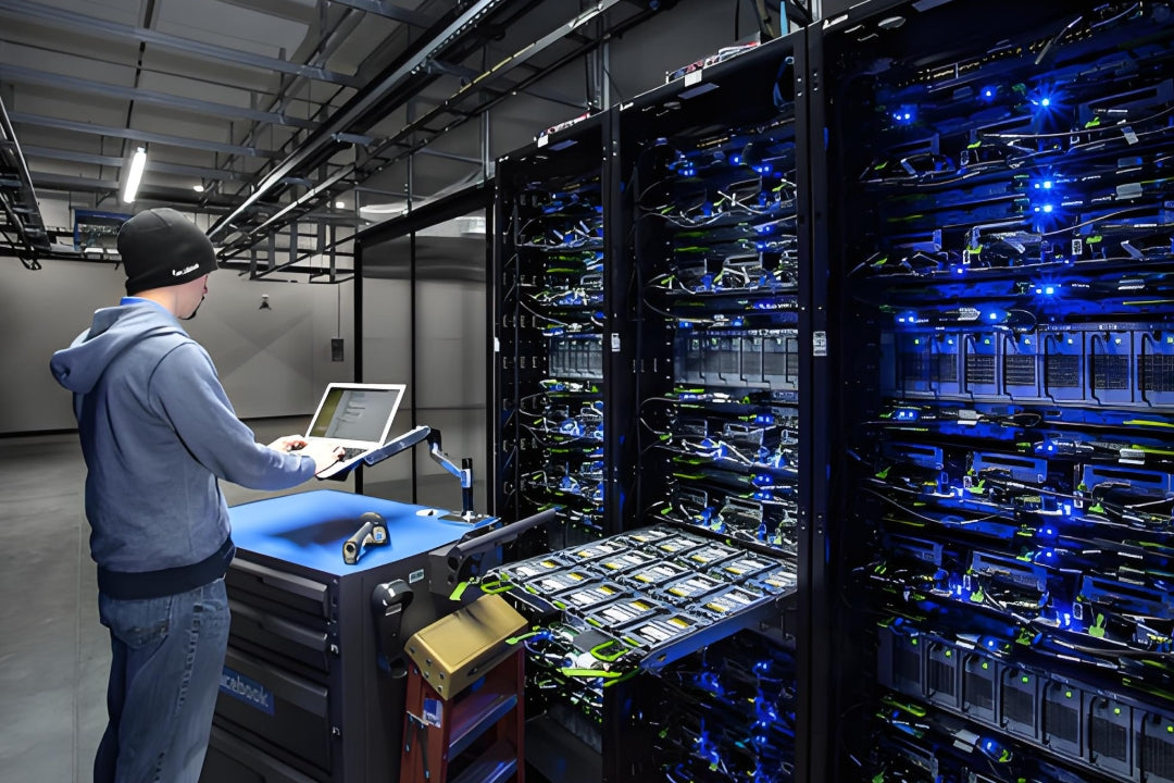
AI training clusters with 64–128 GPUs per rack demand cabling densities that conventional connectors struggle to manage
Key Question
Q: Isn't MPO/MTP already the standard for high-density data center fiber? Why would we change?
A: MPO/MTP remains the backbone standard for data center fiber infrastructure — and that won't change. The shift to CS and other SFF connectors is happening at the edge level — specifically at the switch-to-server and intra-rack connections where 800G/1.6T optical modules terminate. MPO still makes sense for trunk runs; smaller connectors are winning where you need higher port counts per unit of rack space. For background on MPO configurations, see our MPO Fiber Solutions guide.
Chapter 2: MPO/MTP vs. CS vs. LC Duplex — Connector Comparison
Understanding the Connector Landscape
The data center fiber connector family has evolved through distinct generations, each optimized for a specific density and bandwidth challenge:
| Connector | Type | Fiber Count | Typical Use Case | Form Factor | Key Limitation |
|---|---|---|---|---|---|
| LC Duplex | Single-fiber | 2 | Enterprise, switch uplinks | Small (1.25mm ferrule) | High fiber count at 800G+ |
| MPO/MTP-12 | Multi-fiber | 12 | 40G/100G/400G SR4, 800G SR8 | Standard (6.4mm width) | Large for high port counts |
| MPO/MTP-24 | Multi-fiber | 24 | 400G SR4 (2x12), futureproofing | Standard+ (8.2mm width) | Higher insertion loss vs 12-fiber |
| CS | Duplex/Single | 2 | 800G DR8/FR8, 1.6T (4x400G) | Ultra-small (2.45mm pitch) | Limited ecosystem vs LC |
| SN | Duplex | 2 | 800G DR8, dual-row MDC alternative | Ultra-small (3.0mm pitch) | Emerging, less market share |
| MDC | Duplex | 2 | Ultra-high density (breakout) | Micro-duplex (1.25mm) | Very fragile, field limited |
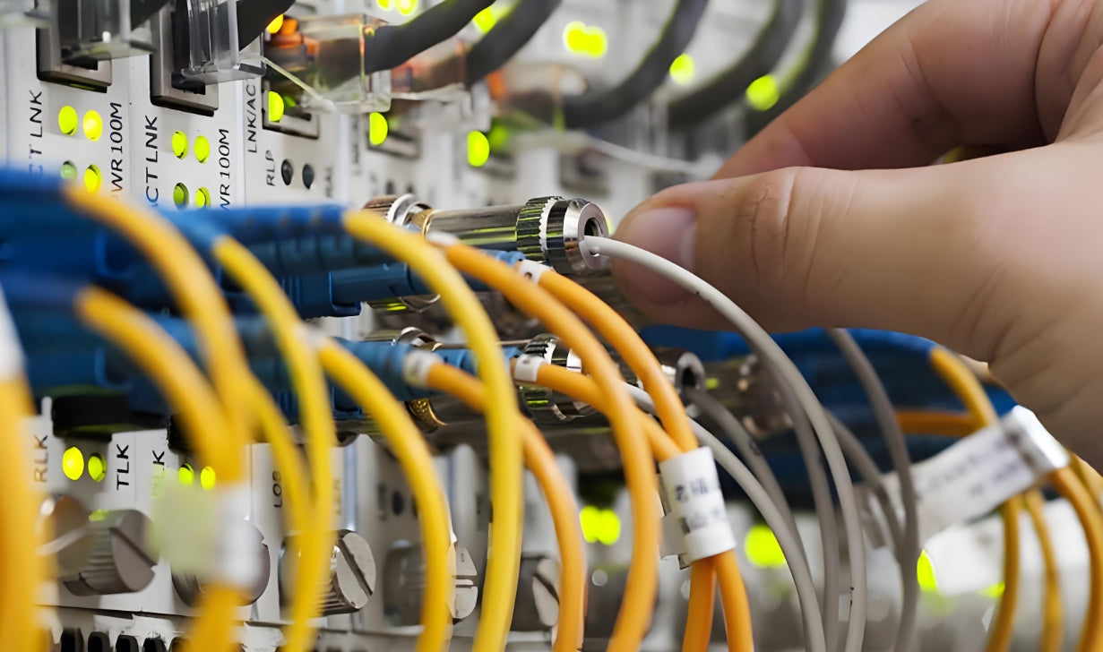
The connector landscape is evolving from MPO dominance toward a mix of SFF options optimized for different deployment scenarios
Why CS is Gaining Ground
The CS (Cloud-Scale) connector was developed specifically for high-port-count 800G and 1.6T deployments. Its pitch (center-to-center spacing of 3.55mm vs LC's 6.25mm) allows approximately 2.5x the port density in the same rack unit compared to LC duplex. Key advantages:
- Direct attachment to 800G DR8/FR8 modules: CS was designed alongside the 800G optical module spec — many 1.6T and 800G OSFP and QSFP-DD form factor modules use CS as their native connector
- Duplex integrity: Unlike MPO (which fans out multiple fibers at once), CS maintains true duplex polarity management — critical for bidirectional traffic at 800G+ speeds
- Rack-level cable management: Smaller diameter cords (typically 2.0mm jacket vs 3.0mm for MPO-based assemblies) reduce cable fill ratios in overhead and under-floor routing
Key Question
Q: How does CS compare to LC in terms of optical performance?
A: CS uses the same 1.25mm ferrule as LC, meaning optical performance is essentially identical — typical insertion loss of 0.15–0.35 dB and return loss >45 dB for single-mode applications. The difference is purely physical. CS connectors are typically rated for the same number of mating cycles (500+) as LC. For the practical implications of connector selection on signal integrity, see Strategic Fiber Selection.
Chapter 3: Where CS Connectors Are Winning in 800G/1.6T Deployments
Deployment Scenario 1: AI Training Clusters (DR8/FR8 Top-of-Rack)
AI training clusters use DR8 (500m, single-mode) or FR8 (2km, single-mode) optical modules for GPU-to-GPU and GPU-to-switch interconnects. These modules typically terminate in CS or LC duplex connectors. At 64 GPUs per rack, the port density challenge is acute:
- With LC duplex: 128 ports per rack (64 GPUs × 2 ports each) — manageable but cable routing is complex
- With CS duplex: Same 128 ports, but at 2.5x the density — cables fit through narrower pathways and bend radius limits are easier to manage
Deployment Scenario 2: 1.6T Switch Uplinks
First-generation 1.6T switches use 64x 200G lanes (8x200G per port using 200G PAM4 optics). The 1.6T OSFP and QSFP-DD1600 form factors typically support CS or MPO native connectors. For switch-to-switch interconnects at the spine level, MPO remains preferred (backbone trunk economy). But for switch-to-server (leaf) connections, CS is emerging as the connector of choice.
Deployment Scenario 3: Mixed 800G/1.6T Migration
For data centers upgrading incrementally from 800G to 1.6T, mixed-connector architectures are common:
- New 1.6T spine switches: Deploy with MPO-24 or CS-based modules
- 800G TOR switches: Mix of LC duplex (legacy) and CS (new)
- Adapter solutions: CS-to-LC and CS-to-MPO adapters provide migration flexibility
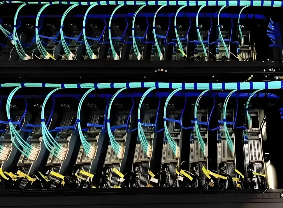
Modern AI data centers require connector strategies that support both current 800G deployments and the 1.6T migration ahead
AMPCOM Cabling Solutions for High-Density 800G/1.6T Deployments
SC-to-SC Fiber Patch Cables: OS2 single-mode and OM4 multimode assemblies for 800G/1.6T DR8/FR8 connections
SC-to-LC Hybrid Cables: For mixed-connector migration environments, maintaining backward compatibility
SC-to-MPO Adapter Panels: High-density adapter panels enabling MPO backbone to SC edge transitions
OM4/OM5 Multimode SC Assemblies: For short-reach intra-rack GPU cluster connections
Custom Length Manufacturing: Fast turnaround for project-specific SC assembly lengths
See also: What 800G and 1.6T Trends Mean for Data Center Cabling in 2026.
Key Question
Q: Should we standardize on CS or keep LC as our default duplex connector?
A: It depends on your upgrade timeline. If you're actively deploying 800G/1.6T now or in the next 12 months, CS is worth adopting — particularly for new builds and new rack deployments. If your 800G migration is 2+ years out, you may prefer to stick with LC duplex and wait for the CS ecosystem to mature further. LC-to-CS adapter solutions provide a bridge if you need to go LC now but expect CS growth later.
Chapter 4: Migration Strategies — Planning Your Transition
Strategy 1: Separate Backbone and Edge Connector Standards
The cleanest migration path is to keep MPO as your backbone standard (which remains the most cost-effective solution for trunk runs of 10m and above) and adopt CS or LC at the edge. Your transition points are:
- MPO trunk → CS patch panel: MPO-to-CS fan-out panels at the row terminus
- CS-to-server connections: Short CS patch cords (1–5m) from the panel to the optical module
Strategy 2: Plan for Polarity Management
CS duplex connectors maintain standard TIA-568 polarity (A-to-B), but in high-count deployments, polarity errors are a significant source of network faults. Use keyed CS connectors and maintain strict polarity documentation — a 512-fiber deployment with CS connectors can take days to debug if polarity isn't tracked.
Strategy 3: Don't Over-Specify — Match Connector to Reach
| Reach | Fiber Type | Recommended Connector | Module Type |
|---|---|---|---|
| Intra-rack (<100m) | OM4/OM5 multimode | CS duplex or LC duplex | SR8, DR8 |
| Inter-rack (100m–500m) | OS2 single-mode | CS duplex or MPO-12 | DR8, FR8 |
| Row/zone (500m–2km) | OS2 single-mode | MPO-12 or CS duplex | FR8, LR8 |
| Spine/backbone (2km+) | OS2 single-mode | MPO-24 | LR8, ER8 |

Matching connector type to reach ensures optimal cost-performance tradeoffs across the data center cabling hierarchy
Key Question
Q: What testing standards apply to CS connector deployments?
A: The same IEC 61300 and TIA-568 standards that apply to LC and MPO connectors apply to CS. For single-mode deployments, use an OTDR to verify end-to-end insertion loss (max 0.35 dB per connection for OS2 CS assemblies). For multimode, use an Encircled Flux compliant light source and power meter. CS connector end-face inspection (using a CS-compatible probe) is essential — debris on the 1.25mm ferrule face is the leading cause of failures in high-density deployments. See our Fiber Cabling for Sustainable Data Centers for more on testing best practices.
Conclusion
The shift from MPO/MTP toward CS and other smaller-form-factor connectors is not a revolution — it's an evolution driven by the specific demands of 800G and 1.6T port density. MPO remains the backbone standard; CS is winning at the edge. The key is to understand where each connector type delivers the most value, plan your migration with hybrid architectures in mind, and work with a cabling partner who can supply the full connector ecosystem from day one.
Related Articles
- MPO Fiber Solutions for Data Center and High-Density Cabling — Choosing 8, 12, or 24-fiber configurations for 800G deployments
- What 800G and 1.6T Trends Mean for Data Center Cabling in 2026 — Market data and infrastructure implications
- Strategic Fiber Selection: Engineering High-Performance Networks — Matching fiber types to deployment scenarios
- 800G Is Not Just a Speed Upgrade — It Changes Which Fiber Designs Remain Manageable — Design principles for 800G fiber infrastructure

AMPCOM Technical Team
Industry experts with 15+ years in data center structured cabling and next-generation connector systems
Ready to plan your 800G/1.6T cabling upgrade?
Contact AMPCOM's technical team for a complimentary connector specification review and migration roadmap consultation.
Get Free Consultation

