
Fiber Optic Patch Cables: The Complete 2026 Buyer's Guide
Published:
Executive Summary: With data center traffic doubling every three years and enterprise networks pushing toward 400G and 800G speeds, choosing the wrong fiber optic patch cable does more than create a bad connection—it creates a cascading performance bottleneck that haunts your operations team for months. This guide cuts through the jargon: single-mode vs multimode, LC vs MPO, UPC vs APC, and every specification that actually matters when you're spec'ing out a real deployment.
Whether you're cabling a new AI training cluster, upgrading a campus backbone, or just replacing aging patch cords in a colocation cabinet, this guide walks you through every decision point with actionable criteria.
Quick Navigation
- 1 What Is a Fiber Optic Patch Cable?
- 2 Single-Mode vs. Multimode Fiber
- 3 Connector Types: LC, SC, MPO, and More
- 4 Polish Types: UPC vs. APC
- 5 Cable Jacket Types and Ratings
- 6 Key Performance Specifications
- 7 How to Choose the Right Patch Cable
- 8 Common Selection Mistakes to Avoid
- 9 Key Questions Answered

High-density fiber patching in a modern enterprise data center—connector selection and cable management directly impact network reliability
1. What Is a Fiber Optic Patch Cable?
A fiber optic patch cable (also called a fiber jumper or fiber patch cord) is a section of optical fiber cable with connector terminations on both ends, designed for flexible, short-distance interconnections within an optical network. Unlike backbone trunk cables—which are typically multi-fiber, heavy-gauge, and permanently installed—patch cables are the dynamic layer: they connect servers to switches, patch panels to equipment ports, and cross-connect fiber routes in colocation environments.
The distinction matters practically:
- Fiber patch cable — connectors on both ends, reusable, typically 1–15 meters, deployed in racks and at cross-connects
- Fiber pigtail — connector on one end only, fusion-spliced or mechanically terminated at the other, used for permanent splice points
- Trunk cable — multi-fiber backbone, usually MPO-terminated, runs between distribution frames over long distances
In an enterprise data center, patch cables are the most frequently touched components in the entire physical layer. A well-selected patch cable performs consistently across thousands of mating cycles. A poor selection—wrong mode, wrong connector, wrong jacket—creates chronic insertion loss events that erode network margins and drive up Mean Time To Resolution (MTTR) for connectivity incidents.
Typical Applications for Fiber Patch Cables
Intra-rack connections: Server NIC to top-of-rack (ToR) switch via LC duplex or MPO breakout
Inter-rack connections: Horizontal patching between row distribution frames and spine switches
Cross-connect frames: Structured patching in main distribution areas (MDA) for colocation and enterprise IDF/MDF
FTTH/building entry: Indoor-outdoor transition cables connecting outside plant to customer premise equipment
Test and measurement: Connecting OTDR, power meters, and light sources to active links during commissioning and troubleshooting
2. Single-Mode vs. Multimode Fiber
This is the foundational decision in any fiber deployment, and it is governed by a single variable: the core diameter of the optical fiber. The core is the light-carrying center of the fiber—the diameter determines how many distinct light paths (modes) the signal can take as it travels through the cable.
2.1 Single-Mode Fiber (OS1/OS2)
Single-mode fiber has a core diameter of approximately 8–10 microns (μm). Light travels in essentially one path through the core, which eliminates modal dispersion—the phenomenon where different light modes arrive at the receiver at slightly different times, distorting the signal.
Because single-mode eliminates modal dispersion, it achieves dramatically higher bandwidth and longer reach than multimode:
- Maximum Ethernet distance: 120km at 10G, 80km at 100G, 40km at 400G (with coherent optics extending to thousands of kilometers)
- Operating wavelengths: 1310nm (O-band) and 1550nm (C-band) — both longer than visible light
- Cable jacket color: ● Yellow (industry standard for OS1 and OS2)
- Transceiver cost: Higher than multimode (DFB/EML lasers vs. VCSELs)
2.2 Multimode Fiber (OM1–OM5)
Multimode fiber has a larger core diameter—50 μm or 62.5 μm—which allows multiple light modes to propagate simultaneously. This makes multimode cheaper to operate (VCSEL laser transceivers are a fraction of DFB laser cost), but limits reach and bandwidth due to differential mode delay (DMD).
| Grade | Core Diameter | Jacket Color | Max Distance @ 10G Ethernet | Best Use Case |
|---|---|---|---|---|
| OM1 | 62.5 μm | Orange | 33m | Legacy 1G–10G, mostly phased out |
| OM2 | 50 μm | Orange | 82m | Legacy 1G–10G, short runs |
| OM3 | 50 μm | Aqua / Teal | 300m | 10G/40G data center, laser-optimized |
| OM4 | 50 μm | Aqua / Teal | 400m | 10G/40G/100G data center |
| OM5 | 50 μm | Lime Green / Violet | 400m | Short-wave WDM (SWDM4) at 40G/100G |
Decision Scenario: Intra-Data Center vs. Campus Backbone
An enterprise building a new 10,000-square-foot data center with 200 cabinets and 100G uplink requirements faces the classic single-mode vs. multimode decision. The spec: 15-meter average patch cord length, 100G to the aggregation layer, 40G server uplinks in Phase 1, with 400G planned for Phase 3 in 36 months.
For the intra-rack and horizontal patching (under 100 meters), OM4 multimode paired with LC duplex connections delivers the lowest total cost of ownership at 40G. For the aggregation and spine layer where spans exceed 150 meters, single-mode OS2 becomes the practical choice. The optimal architecture uses multimode in the access layer, single-mode in the backbone—matching the cable plant to the reach requirement at each tier.
2.3 Singlemode vs. Multimode at a Glance
| Specification | Single-Mode (OS2) | Multimode (OM3/OM4) |
|---|---|---|
| Core Diameter | 9 μm | 50 μm |
| Cladding Diameter | 125 μm | 125 μm |
| Jacket Color | Yellow | Aqua (OM3/OM4), Lime Green (OM5) |
| Operating Wavelength | 1310nm / 1550nm | 850nm / 1300nm |
| Max Ethernet Distance (10G) | Up to 40km (LRM), 120km (LR) | Up to 400m (OM4) |
| Transceiver Cost | Higher | Lower (VCSEL-based) |
| Typical Application | Long-haul, campus, DCI, 40G+ backbone | Intra-DC, LAN aggregation, server access |
| Bandwidth Rating | >18,000 MHz·km | 2000 MHz·km (OM3) / 4700 MHz·km (OM4) |

Single-mode (yellow) and multimode (aqua) patch cables serve different reach and application requirements in enterprise networks
3. Connector Types: LC, SC, MPO, and More
Fiber connector selection determines port density, compatibility with transceiver form factors, and the complexity of your structured cabling design. The three dominant connector families in modern enterprise networks are LC duplex, MPO/MTP multi-fiber, and SC simplex/duplex.
3.1 LC — Lucent Connector (Most Common Today)
The LC connector is the dominant choice in modern enterprise and data center networks. Its 1.25mm ferrule—roughly half the diameter of an SC ferrule—delivers twice the port density in the same rack unit. LC uses a push-pull mechanism with a latch that audibly clicks into place, making it fast to deploy and reliable in high-density environments.
Key specifications:
- Ferrule diameter: 1.25mm (half the size of SC's 2.5mm)
- Typical use: QSFP-DD, SFP+ transceivers, LC-style patch panels
- Polarity: Duplex (Tx/Rx on two separate ferrules in one housing)
- Dominant in: 10G, 25G, 40G, 100G, 400G, 800G deployments
3.2 MPO/MTP — Multi-Fiber Push-On
The MPO/MTP connector terminates 8, 12, 16, 24, or 32 fibers in a single rectangular ferrule. This dramatically reduces the physical footprint of high-fiber-count connections—twelve LC duplex pairs can be replaced by a single 24-fiber MPO. MPO/MTP is the standard for parallel optics at 40G, 100G, and 400G Ethernet.
| MPO Type | Fiber Count | Typical Use Case | Key Application |
|---|---|---|---|
| MPO-8 | 8 fibers | 40G SR4 / 100G SR4 | 4×10G or 4×25G lanes via breakout |
| MPO-12 | 12 fibers | 40G SR4, 100G SR10, 400G DR4 | Most common backbone trunk type |
| MPO-24 | 24 fibers | 100G SR4 extended, 400G-SR4.2 | Higher density parallel optics |
| MPO-16 / 32 | 16 / 32 fibers | 400G FR4/LR4, emerging 800G | Next-generation high-speed optics |
3.3 SC — Subscriber Connector
The SC connector was the dominant enterprise connector through the 1990s and early 2000s, defined by its 2.5mm ceramic ferrule and push-pull snap-in mechanism. It remains common in legacy enterprise infrastructure, passive optical networks (PON/GPON), and certain industrial applications. Modern data centers have largely migrated to LC for access-layer connections and MPO for backbone.
3.4 MDC and CS — Next-Generation Mini Connectors
As port counts climb toward 400G and 800G per rack unit, two emerging connector form factors are gaining rapid adoption: MDC (Mini Duplex LC) and CS. Both deliver approximately double the port density of standard LC by using a reduced-form-factor duplex housing. They are becoming critical for 800G-FR4 and 800G-LR4 QSFP-DD and OSFP transceiver implementations where rack space constraints make standard LC density insufficient.
Connector Type Quick Reference
LC duplex: Default choice for 10G–100G SFP/SFP+ and QSFP28 access ports. Most versatile, broadest compatibility.
MPO-12: Standard for 40G SR4 and 100G SR10 trunk cables. Preferred backbone connector for parallel optics.
SC: Legacy installations, GPON/NG-PON2 ONTs, and RFoG systems. Not recommended for new greenfield deployments.
MDC/CS: Emerging standard for 400G/800G ultra-high-density rack deployments. Verify transceiver and switch compatibility before specifying.
FC: Laboratory and test equipment, high-vibration industrial settings. Screw-lock mechanism provides maximum retention security.
4. Polish Types: UPC vs. APC
The polish type refers to the geometry of the connector end face—the physical surface that contacts the mated ferrule. Polish type determines return loss: how much optical signal reflects back toward the source rather than continuing down the fiber. Return loss is a critical performance parameter in high-speed, long-reach, and wavelength-sensitive systems.
4.1 PC — Physical Contact (Legacy)
PC polish features a slightly spherical end-face radius that brings the fiber cores into physical contact at the center of the ferrule. This was the first practical approach to reducing return loss compared to flat-face connectors. PC polish achieves approximately −40 dB return loss, which was acceptable for early 1310nm laser systems but is insufficient for modern high-speed applications.
4.2 UPC — Ultra Physical Contact
UPC polish extends the radius of the PC end face, creating a more refined convex surface that improves core-to-core contact and reduces surface defects. The result is approximately −55 dB return loss. UPC is the standard for most enterprise network applications—digital transmission, Ethernet switches, and router interconnects. It delivers excellent return loss at a lower cost than APC while remaining compatible with standard PC/UPC connectors.
Color coding: Blue housing for both PC and UPC (though UPC may have a slightly lighter blue depending on the manufacturer).
4.3 APC — Angled Physical Contact
APC polish is the premium option for return-loss-sensitive applications. The ferrule end face is polished at an 8-degree angle relative to the fiber axis. This angled geometry directs any reflected light into the cladding rather than back into the fiber core, achieving −65 dB or better return loss—more than 10× better than PC.
APC is required or strongly preferred for:
- CATV and RFoG distribution (analog video is extremely sensitive to back-reflection)
- Coarse/dense wavelength division multiplexing (CWDM/DWDM) systems
- Long-reach single-mode links where the optical signal-to-noise ratio is critical
- High-speed serial links at 28G+ baud rates
Color coding: Green housing (industry standard for APC worldwide).
Critical Warning: Never Mate APC with UPC
Connecting an APC connector to a UPC or PC connector is one of the most damaging mistakes in fiber deployment. The 8-degree angled ferrule of an APC connector will physically grind against the flat or UPC convex surface of the mated connector, destroying both end faces within a few insertions. The resulting contamination and pitting causes insertion loss exceeding 3–5 dB and return loss performance collapses entirely. Always verify polish type before mating—and when in doubt, inspect with a fiber microscope first.
| Polish Type | End-Face Geometry | Return Loss | Connector Color | Primary Applications |
|---|---|---|---|---|
| PC | Spherical, slight convex | ~−40 dB | Beige / Blue | Legacy, mostly phased out |
| UPC | Extended convex, refined | ~−55 dB | Blue (light) | Enterprise Ethernet, data centers, most digital applications |
| APC | 8-degree angled | ~−65 dB or better | Green | CATV, DWDM/CWDM, long-haul, high-speed serial |
5. Cable Jacket Types and Ratings
The cable jacket protects the optical fiber from physical damage, moisture, chemical exposure, and fire hazards. Selecting the correct jacket type is not optional—it is mandated by building codes, safety standards, and environmental conditions in most enterprise and colocation deployments.
5.1 Jacket Material Types
| Jacket Type | Full Name | Key Characteristics | Primary Use Environment |
|---|---|---|---|
| PVC | Polyvinyl Chloride | Standard flexibility, low cost, not fire-rated | Standard indoor use, under-floor, in-rack patching |
| LSZH | Low Smoke Zero Halogen | Minimal toxic gas in fire, low smoke, flame-retardant | European data centers, tunnels, airports, public buildings |
| OFNP | Optical Fiber Nonconductive Plenum | Highest fire rating, no conductive materials, plenum-rated | Air-handling spaces (HVAC plenums, raised floors) |
| OFNR | Optical Fiber Nonconductive Riser | Flame-retardant for vertical runs between floors | Vertical shafts, between-floor riser pathways |
| Armored | Corrugated Steel Armor | Steel interlocked or corrugated sheath, rodent and crush resistant | Outdoor, industrial, campus, harsh environments |
5.2 How to Choose Jacket Type
Jacket Selection Decision Guide
Standard indoor racks and underfloor: PVC or LSZH duplex/triplex zipcord. PVC is most cost-effective for indoor climate-controlled environments. Choose LSZH if your facility has strict fire safety codes or is in a European market.
Air-handling plenum spaces (raised floor void, HVAC duct): OFNP is mandatory per NEC Article 770. The cable must be specifically rated as nonconductive and plenum-appropriate—using standard PVC in a plenum space is a code violation that can fail building inspections.
Vertical riser between floors: OFNR minimum. OFNR-rated cables prevent flame propagation in vertical shaft installations where fire travels upward fastest.
Outdoor or partially outdoor environments: Armored with UV-resistant polyethylene jacket. Look for gel-filled loose-tube construction for underground runs and anti-UV additives for aerial or facade-mounted sections.
Industrial/factory environments: Armored LSZH or OFNP with oil and chemical resistance ratings per IEC 60794-1-2. Verify the specific chemical exposure profile against the cable manufacturer's datasheet.
6. Key Performance Specifications
Beyond connector type and fiber mode, the specifications that determine real-world link performance are insertion loss (IL) and return loss (RL). These two parameters directly determine whether a link operates within its optical power budget.
Insertion Loss
Insertion loss measures the total optical power lost as light passes through a connector, splice, or link segment. It is expressed in decibels (dB)—and unlike copper attenuation, which is linear, fiber insertion loss follows the logarithmic dB scale: every 3 dB of loss cuts the signal power in half.
| Component / Link Type | Standard Insertion Loss (Max) | Low-Loss Insertion Loss (Max) | Test Standard |
|---|---|---|---|
| LC / SC / FC Connector (single insertion) | ≤ 0.30 dB | ≤ 0.15 dB | IEC 61300-3-34 |
| MPO/MTP Connector (per fiber) | ≤ 0.35 dB (MM), ≤ 0.50 dB (SM) | ≤ 0.20 dB | IEC 61300-3-34 |
| Mechanical Splice | ≤ 0.50 dB | ≤ 0.30 dB | IEC 61300-3-32 |
| Fusion Splice | ≤ 0.15 dB | ≤ 0.05 dB | IEC 61300-3-32 |
| Multimode Link Budget (OM4, 100m) | ≤ 1.9 dB total | — | IEEE 802.3ba / 802.3bm |
| Single-Mode Link Budget (OS2, 10km) | ≤ 6.3 dB total | — | IEEE 802.3ae |
Return Loss
Return loss measures how much light is reflected back toward the source. High return loss (a large negative dB number) is desirable—it means minimal reflection. Return loss is particularly critical for:
- Laser transmitters (reflections can destabilize the source and increase bit error rate)
- Single-mode long-reach links operating near their power budget ceiling
- DWDM/CWDM systems where back-reflection degrades wavelength isolation
- CATV analog video distribution where any reflection creates ghosting
Calculating Your Optical Link Budget
Every fiber link has a defined power budget—the maximum total loss the link can tolerate while maintaining reliable communication. The budget is calculated by subtracting the receiver sensitivity (the weakest signal the transceiver can detect) from the transmit power (the strongest signal the source launches).
Example (10G Ethernet over OM4, 150m):
- Transmit power: +3 dBm (typical SFP+ 850nm)
- Receiver sensitivity: −11 dBm (10GBASE-SR minimum)
- Optical power budget: 14 dB
- Estimated fiber attenuation: 3.5 dB/km × 0.15km = 0.525 dB
- 2× LC connector pairs (patch cords): 2 × 0.3 dB = 0.6 dB
- 4× MPO/LC breakouts (in cabinet): 4 × 0.3 dB = 1.2 dB
- Total estimated loss: 2.325 dB
- Margin remaining: 14 − 2.325 = 11.675 dB (healthy margin for future connector degradation)
Aim for minimum 3 dB margin above the calculated total loss. If your estimated loss approaches the budget limit, switch to low-loss connectors or reduce the number of patch connections in the link.
7. How to Choose the Right Patch Cable
Selecting the right fiber patch cable is a systematic process that begins with understanding your application architecture, not with browsing a catalog. Follow this five-step framework:
Step-by-Step Patch Cable Selection
Step 1: Define the link architecture. Is this an access-layer server-to-switch connection, an aggregation backbone, a cross-connect patch, or a test lead? Each application implies different length, density, and durability requirements.
Step 2: Choose the fiber type. Match the patch cable fiber type to your transceiver and cable plant: OM4 for intra-DC 10G–100G links under 400 meters, OS2 single-mode for links exceeding 500 meters or any 40G+ long-reach backbone.
Step 3: Match the connector to the transceiver form factor. QSFP28/QSFP-DD ports use LC duplex or MPO-12 depending on the optical module type. Verify the transceiver datasheet—SR4 uses MPO, SR10 uses MPO, DR4/FR4 use LC duplex or MPO-12. Mismatched connectors are the leading cause of "fiber cable doesn't fit" incidents on the data center floor.
Step 4: Verify polish type compatibility. All connectors in a given link must use the same polish type. Standard enterprise Ethernet: UPC. DWDM/CATV/sensitive analog: APC. Never mix UPC and APC connectors in the same link.
Step 5: Specify the correct jacket rating. OFNP for plenum spaces, OFNR for risers, LSZH for European installations or public buildings, PVC for standard indoor, armored polyethylene for outdoor or industrial. Building inspection failures due to wrong jacket type are entirely preventable.
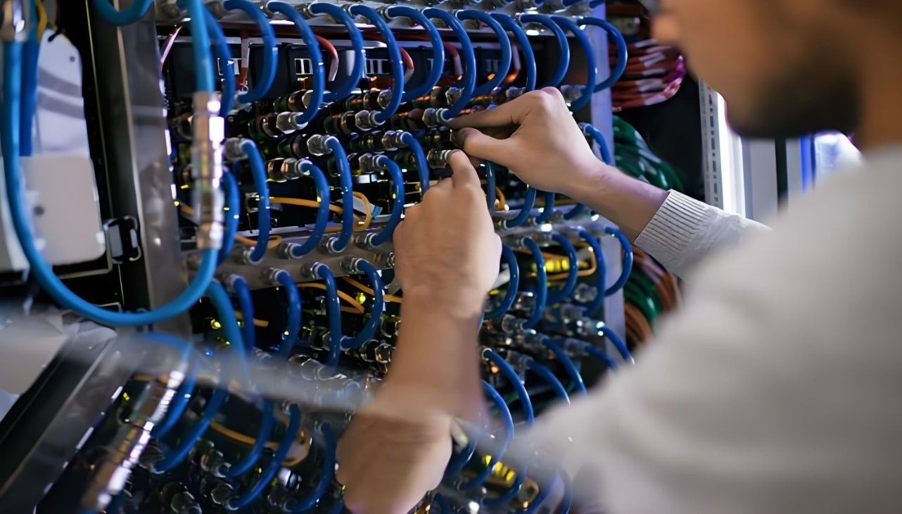
Choosing the right fiber patch cable means matching connector type, fiber grade, polish type, and jacket rating to your specific application requirements
8. Common Selection Mistakes to Avoid
After working with enterprise networks for over two decades, the AMPCOM technical team has catalogued the mistakes that appear most frequently in fiber infrastructure deployments. Here are the most consequential ones to watch for:
Mistake 1: Mixing Singlemode and Multimode in the Same Link
A multimode transceiver launching 850nm VCSEL light into a single-mode fiber core creates an extreme modal mismatch—the 50μm-to-9μm diameter difference results in 20+ dB of coupling loss. The link simply fails to pass traffic. Conversely, launching single-mode 1310nm laser light into a 50μm multimode core creates excessive differential mode delay and modal noise at the receiver.
Prevention: Document the fiber type on every cable label and cross-reference against the transceiver module's specified fiber type before installation.
Mistake 2: Specifying Standard Loss When Low-Loss Is Needed
Standard-loss LC connectors (≤ 0.30 dB per mated pair) consume significant loss budget when a link has multiple patch connections. A 10G OM4 link with 6 connector pairs—a realistic count in a structured patching environment—consumes 1.8 dB of a 2.6 dB total budget, leaving almost no margin for connector aging or contamination events.
Prevention: Specify low-loss connectors (≤ 0.15 dB) for any link where the total connector count exceeds four, or where the link approaches 70% of the maximum distance for its fiber grade.
Mistake 3: Ignoring MPO Polarity
MPO trunk cables support three polarity schemes (Type A, Type B, and Type C), and an incorrectly configured polarity scheme reverses the transmit/receive pairs across the entire trunk. The result: a "correctly" wired MPO backbone that passes continuity testing but fails traffic because every fiber pair is reversed.
Prevention: Document the polarity scheme in the design phase. Type A (straight-through) is the most common and simplest to manage. Verify polarity with a visual fault locator or power meter before commissioning any MPO backbone.
Mistake 4: Storing Excess Patch Cord Slack Improperly
Excess patch cords coiled behind a cabinet and tucked into cable managers create micro-bend losses when loops are too tight or when cables are compressed by adjacent bundles. A 3-meter patch cord stored as a compressed figure-eight behind a cabinet will perform measurably worse than the same cable properly dressed as a gentle service loop.
Prevention: Plan patch cord lengths from actual rack measurements. For horizontal patching, target 1.5–3 meter lengths in most cabinets. If slack is unavoidable, use dedicated fiber slack management spools or trays, never compress coils behind equipment.
The Cost of Getting It Wrong
Consider the economics: a single incorrect patch cable specification—a wrong connector type, an incompatible polish, a non-plenum-rated jacket in a plenum space—typically costs $50–$200 per cable to replace. That seems manageable. But in a 2,000-cabinet data center with 8–12 patch cables per cabinet, the exposure is $800,000–$4.8 million in cable replacement risk. Add the operational impact—network downtime during re-cabling, engineering time, and potential SLA penalties—and the economics of correct initial specification become obvious.
Key Questions Answered
Common Questions About Fiber Optic Patch Cables
A: No. Single-mode and multimode fiber are fundamentally incompatible in the same link due to different core diameters (9μm vs. 50μm) and different operating wavelengths (1310nm/1550nm vs. 850nm/1300nm). The coupling loss from mode mismatch will exceed 20 dB—effectively zero light reaching the receiver. Always match the patch cable fiber type to the transceiver's specified fiber type.
A: For structured patching within a data center, patch cables typically range from 1–15 meters. The IEEE 802.3 Ethernet standard specifies maximum channel distances (up to 400m for OM4 at 10G), but this includes the entire channel—horizontal cable, equipment cords, and consolidation point connections. As a practical rule, limit individual patch cords to 10 meters or less; longer horizontal runs should use permanent installed cable plant (trunk cables) rather than patch cords.
A: UPC (Ultra Physical Contact) provides approximately −55 dB return loss and is the standard for most enterprise Ethernet applications. APC (Angled Physical Contact) provides −65 dB or better return loss with its 8-degree angled end-face. Use APC for CATV/analog video, DWDM/CWDM wavelength systems, and any link where back-reflection would destabilize the laser source or degrade wavelength isolation. Never mate APC with UPC connectors—it will damage both end faces.
A: LC duplex is the default for 10G, 25G, 40G (QSFP+ with LC ports), 100G (QSFP28 with 4×25G LC breakouts), and 400G FR4/LR4 transceivers. MPO/MTP is the choice for 40G SR4, 100G SR10, 400G SR4, and 400G DR4 transceivers that use parallel optics—where multiple fibers carry parallel data lanes simultaneously. If your switch ports are QSFP-DD with LC ports, use LC duplex. If they are QSFP-DD with MPO ports, use MPO-12 or MPO-16.
A: For standard under-floor cable routing in climate-controlled data centers, PVC or LSZH zipcord jackets are typically sufficient for patch cables. However, if your raised floor is designated as a supply air plenum (where conditioned air circulates through the floor void), NEC Article 770 requires OFNP-rated cables. Check your facility's electrical and mechanical codes—using non-plenum-rated cables in a plenum space is a code violation that can trigger inspection failures and fire safety citations.
A: Properly handled fiber patch cables can withstand hundreds to thousands of mating cycles without significant performance degradation. However, every insertion generates micro-wear on the connector end face, and contamination events accelerate wear dramatically. Best practice: inspect every connector under a microscope before each mating cycle in high-reliability environments, and replace patch cables that show visible scratches, pits, or contamination defects—typically on a 2–5 year replacement cycle in high-traffic cross-connect frames.
A: Specify standard-loss (≤ 0.30 dB) connectors for links with fewer than four total mated pairs and comfortable loss budget margins. Specify low-loss (≤ 0.15 dB) connectors for links approaching maximum distance, links with four or more connector pairs, or any link where the optical power margin is less than 5 dB. Low-loss connectors cost approximately 20–30% more but can be the difference between a reliable link and a marginal one that fails when connector performance degrades with age and contamination.
A: MPO polarity schemes (Type A, B, or C) define how transmit and receive fibers are mapped across the trunk. Type A (straight-through) maps fiber 1 to fiber 1, fiber 2 to fiber 2, etc.—the simplest scheme. Type B (reverse) flips transmit and receive at both ends. Type C (pair flip) swaps adjacent pairs at one end. For most enterprise data center deployments, Type A is preferred for its simplicity. Always verify your transceiver module's polarity requirements and document the polarity scheme in your as-built records before commissioning the link.
Related Articles
- MPO Fiber Solutions: Choosing 8, 12, or 24 Fibers for High-Density Cabling — Selecting the right MPO configuration for your 40G/100G/400G parallel optics deployment
- How to Choose the Right Fiber Type: Singlemode vs Multimode — OM3/OM4 vs OS2: matching fiber type to link speed and distance for enterprise networks
- How AI Infrastructure Is Reshaping Data Center Cabling Requirements — Why AI training clusters demand OM5 multimode and high-density MPO patching
- Structured Cabling for AI Data Centers: What Is Changing — Key differences between traditional and AI-optimized structured cabling architectures

AMPCOM Technical Team
Industry experts with 17+ years in enterprise fiber optic infrastructure and network cabling solutions
Need help selecting the right fiber patch cables for your network?
Our technical team provides free consultation, product matching, and customized cabling solutions for enterprise data centers, colocation facilities, and campus networks.
Get Free Consultation

