
Optical Distribution Frame Guide: ODF for Data Centers
Published:Executive Summary: Without the right ODF, your fiber network becomes a tangled mess that takes hours to troubleshoot and introduces insertion loss you can't afford. This guide walks enterprise network architects and data center managers through every ODF type, component, installation step, and maintenance practice that keeps fiber infrastructure reliable at scale.
Whether you're deploying a new AI-ready data center or upgrading a telecom switching room, understanding optical distribution frame design separates maintainable networks from fiber spaghetti that nobody wants to touch.
Quick Navigation
- 1 What Is an Optical Distribution Frame (ODF)?
- 2 Types of ODF: Choosing the Right Form Factor
- 3 Key Components Inside an ODF
- 4 ODF in Data Centers: High-Density Fiber Management
- 5 ODF in FTTx and Enterprise Networks
- 6 Installation Best Practices
- 7 Cable Management and Labeling Standards
- 8 Maintenance, Testing, and Troubleshooting
- 9 Key Questions Answered
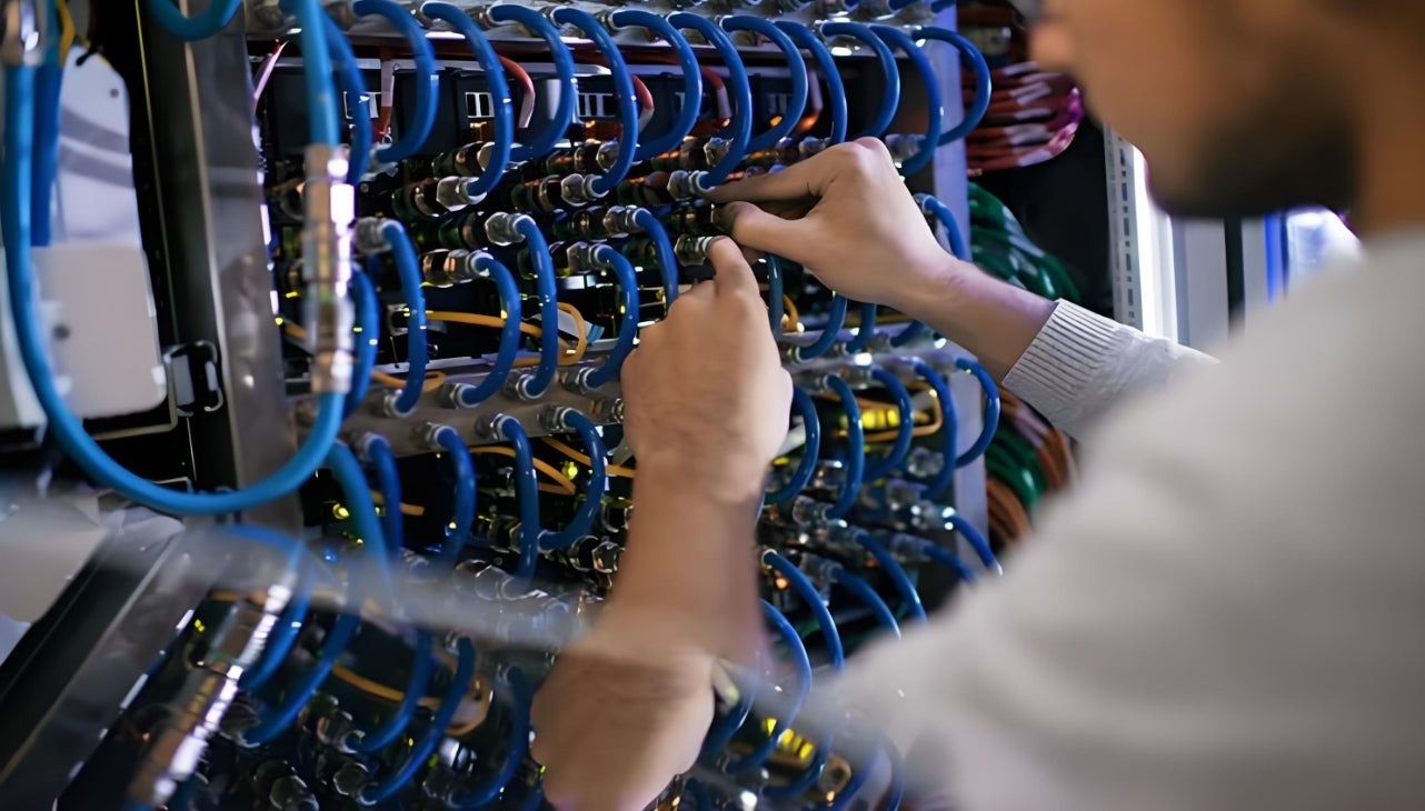
A properly installed ODF organizes hundreds of fiber connections in a structured, maintainable layout
1. What Is an Optical Distribution Frame (ODF)?
An Optical Distribution Frame (ODF) is a centralized fiber management platform that serves as the physical hub for terminating, cross-connecting, and routing optical fibers within a network facility. In plain terms: it is the structured rack or enclosure where every fiber patch cable in your building or data center starts and ends.
Without a well-designed ODF, individual fiber runs from servers, switches, and outside plant cables converge in disorganized bundles that are difficult to trace, maintain, or modify. A properly configured optical distribution frame eliminates that chaos by providing clearly labeled ports, protected splice trays, and organized routing pathways that preserve optical signal integrity.
ODFs are the backbone of structured cabling systems in any facility where fiber optic infrastructure carries mission-critical traffic. They exist at the intersection of optical fiber termination and active equipment patching—the single point where cross-connections can be made or rerouted without disturbing permanent backbone links.
Why the ODF Matters More Than Ever
Modern data centers running 100G QSFP28, 400G QSFP-DD, and 800G OSFP links generate insertion loss budgets that leave almost no margin for error. A poorly dressed patch cord with excessive bend radius violation or a dirty connector can push a link from passing to failing—costing hours of troubleshooting and potentially bringing down a production service. The ODF is your first line of defense against signal degradation.
2. Types of ODF: Choosing the Right Form Factor
Selecting the correct optical distribution frame type depends on your fiber count, available space, environment, and growth trajectory. Here is a side-by-side comparison of the four main ODF categories:
| ODF Type | Typical Fiber Count | Form Factor | Best Use Case | Environment |
|---|---|---|---|---|
| Wall-Mount ODF | 12 – 96 fibers | Compact enclosure, wall-mounted | Telecom rooms, IDF closets, small campus deployments | Indoor, controlled |
| Rack-Mount ODF | 288 – 1,152+ fibers | 19" or 23" rack-mounted chassis | High-density data centers, colocation facilities | Indoor, conditioned |
| Modular / Scalable ODF | Scalable from 96 to 2,000+ | Plug-in modules, expandable chassis | Growing enterprise networks, phased deployments | Indoor, controlled |
| Outdoor ODF | 96 – 576 fibers | Weatherproof cabinet or splice closure | FTTx outside plant, street cabinets, cell tower sites | Outdoor, exposed |
Rack-mount optical distribution frames dominate in enterprise data center environments because they integrate directly into standard server rack rows, use 1U to 4U modular units, and accommodate MPO/LC adapter panels that align with modern high-density fiber patch cables. For colocation facilities and hyperscale deployments, rack-mount ODFs with capacities exceeding 1,000 ports per frame are standard.
Wall-mount ODFs remain practical for smaller telecom rooms, building entrance facilities, or IDF/MDF closets where a dedicated rack row does not justify the cost. They typically hold 12 to 48 ports and rely on splice trays and pigtail assemblies for fiber termination.
3. Key Components Inside an ODF
Understanding the anatomy of an optical distribution frame helps you specify the right configuration and identify what goes missing in cut-rate setups:
| Component | Function | Key Specification |
|---|---|---|
| Rack Chassis / Enclosure | Physical housing that protects all internal fiber components | 19" or 23" standard; 1U–4U height; powder-coated steel |
| Fiber Patch Panels (Adapter Panels) | Hold connector adapters (LC, SC, MPO) for cross-connections | SLIM, MPO, or LC duplex; phosphorus bronze sleeve; ceramic ferrule |
| Splice Trays | Protect fusion or mechanical splices; maintain minimum bend radius | 12–24 splices per tray; G.657.A1 bend radius compliance |
| Cable Management Rings / Guides | Route fibers cleanly without exceeding bend limits | Minimum 30mm bend radius for OS2; vertical and horizontal routing |
| Fiber Pigtails | Pre-connectorized fibers for splicing to backbone cables | 0.9mm or 2.0mm jacket; SC/UPC, LC/UPC, or LC/APC connectors |
| Grounding and Bonding Bar | Electrical grounding for EMI protection and safety | Copper bus bar; grounded to building main bonding busbar |
High-quality ODFs also include dust caps on all unused adapter ports, Velcro-secured routing loops, and clear port labeling strips. Skimping on these details is one of the most common fiber management mistakes in enterprise installations.
4. ODF in Data Centers: High-Density Fiber Management
Data centers running 100G, 400G, and 800G Ethernet require ODFs that can handle hundreds of fibers per rack unit without sacrificing accessibility or introducing signal loss. This is where MPO fiber solutions and modular ODF configurations become essential.
4.1 High-Density MPO-Based ODF
Modern data center ODFs use MPO (Multifiber Push-On) adapter panels to consolidate 12 or 24 fibers per port. A single 1U MPO patch panel provides up to 144 fiber connections (6 × 24-fiber MPO adapters), replacing an entire rack of older LC duplex panels. This density is critical when supporting 100G SR4, 400G SR8, and 800G SR4 transceivers that require parallel optics across multiple fiber pairs.
When planning MPO-based ODF layouts, verify that your insertion loss budget accounts for both the MPO-to-MPO connection at the patch panel and the transceiver-to-patch cord connection at the switch. The combined loss should remain under 1.0 dB for multimode OM4 links at 850 nm, and under 0.5 dB for single-mode OS2 links at 1310 nm.
4.2 Singlemode vs. Multimode ODF Configurations
Both single-mode and multimode fibers terminate in the same ODF chassis, but they demand different adapter types and routing practices:
| Parameter | Single-Mode (OS2) | Multimode (OM4/OM5) |
|---|---|---|
| Core Diameter | 9 μm | 50 μm |
| Typical Wavelength | 1310 nm / 1550 nm | 850 nm / 1300 nm |
| Adapter Type | LC/UPC or LC/APC (green) | LC/UPC or SC/UPC (blue) |
| Return Loss Requirement | ≥ 55 dB (APC); ≥ 45 dB (UPC) | ≥ 20 dB |
| Bend Radius (Installed) | ≥ 15 mm (G.657.A1/A2) | ≥ 30 mm (OM4) |
| Link Distance (100G) | Up to 10 km (LR4) / 40 km (ER4) | Up to 150 m (SR4, OM4) |
Mixed-mode ODF deployments—where single-mode backbone fibers terminate alongside multimode aggregation fibers—require strict physical separation and color-coded labeling to prevent accidental mixing. Experienced data center teams use blue adapters for multimode LC/UPC ports and green adapters for single-mode LC/APC ports as a visual safeguard.

High-density MPO adapter panels in rack-mount ODFs enable hundreds of fiber connections per rack unit
5. ODF in FTTx and Enterprise Networks
While data centers dominate ODF conversations, the technology plays equally critical roles in FTTx (Fiber to the x) architectures and enterprise campus networks.
5.1 FTTx ODF Deployments
In FTTH (Fiber to the Home) and FTTB (Fiber to the Building) networks, the ODF sits at the fiber distribution hub—the point where incoming feeder fibers from the central office are split and routed to individual subscriber drop cables. Here, the optical distribution frame must handle:
- Mass fusion splicing of feeder fibers to distribution fibers using ribbon splice trays
- PLC splitters (1×4, 1×8, 1×16, 1×32 ratios) mounted within or adjacent to the ODF chassis
- Outdoor-rated enclosures that withstand temperature extremes, moisture, and UV exposure
- Documented fiber routing that enables rapid subscriber provisioning and fault isolation
The number of ODF ports required in FTTx deployments scales directly with the number of active subscribers plus a 15–25% growth reserve. Underestimating future port count is among the most expensive fiber network planning mistakes.
5.2 Enterprise Campus ODF
Enterprise campus networks typically deploy a main distribution frame (MDF) ODF at the main telecom room and intermediate distribution frames (IDF) ODFs at each building or floor IDF closet. The MDF ODF handles:
- Termination of outside plant fiber optic cables from service providers
- Cross-connections between carrier circuits and internal enterprise fiber backbone
- Singlemode fiber termination for long-building and inter-building links
- Multimode fiber termination for intra-building horizontal runs
For enterprise networks migrating from legacy Cat6 copper to all-fiber architectures, the ODF transition requires careful planning of patch cord routing between legacy copper patch panels and new fiber adapter panels within the same rack row.
WDM and Coherent Optics Consideration
Enterprises deploying DWDM (Dense Wavelength Division Multiplexing) or coherent optics over single-mode fiber must pay extra attention to ODF connector quality. APC (Angled Physical Contact) connectors with ≥ 55 dB return loss are mandatory for DWDM systems—UPC connectors will reflect enough optical power back into the narrow-bandwidth laser to cause bit errors or transceiver damage over time.
6. Installation Best Practices
A correctly specified ODF delivers poor performance if installed carelessly. These installation best practices separate maintainable fiber infrastructure from disaster-in-waiting:
6.1 Site Preparation
- Verify rack or wall mounting surface can support the full loaded weight — a fully loaded 4U rack-mount ODF with 1,000+ pigtails can exceed 30 kg. Use appropriate mounting hardware and floor anchors where needed.
- Plan cable entry points before installation — route incoming backbone cables to the bottom of the frame to minimize spring tension on fibers. Separate entry points for feeder cables and patch cables prevent cross-contamination of routing zones.
- Ensure environmental conditions — temperature (0°C to 45°C operating range), humidity (non-condensing, ≤ 85% RH), and dust levels. Outdoor ODFs require IP65 or higher ingress protection ratings.
6.2 Fiber Routing Inside the ODF
Routing Rules That Protect Signal Integrity
Maintain minimum bend radius at all times:
- OS2 single-mode: ≥ 15 mm (G.657.A1); ≥ 10 mm (G.657.A2) — G.657.A2 fibers tolerate tighter bends and are preferred for dense ODF routing
- OM3/OM4 multimode: ≥ 30 mm during routing; ≥ 15 mm in splice tray
Use fiber management rings on every vertical and horizontal pathway — never route bare fiber against sharp edges, screw threads, or metal corners without protective grommets.
Reserve service loops — 1 to 2 meters of slack at the ODF entrance and exit ends allows future re-termination or transceiver replacement without pulling on the backbone fiber.
Secure fibers with Velcro straps, never zip ties tightened to the point of crushing the fiber coating. Check retention monthly.
6.3 Grounding and Bonding
Proper ODF grounding prevents ground loops, reduces electromagnetic interference (EMI) from adjacent power cables, and protects technicians during maintenance. The optical distribution frame should be bonded to the building's telecommunications main grounding busbar (TMGB) using a minimum 6 AWG bonding conductor. Verify ground continuity with a multimeter after installation and annually thereafter.

Organized fiber routing within the ODF chassis preserves bend radius and simplifies routine maintenance
7. Cable Management and Labeling Standards
Labeling is not optional. In any facility with more than 48 fiber ports, unlabeled or inconsistently labeled ODF ports create a maintenance nightmare that costs more in technician time than the labeling system itself.
7.1 Port Labeling Standards
Use a consistent, hierarchical labeling code that encodes location, panel, and port number. A common standard follows this pattern:
| Label Element | Example | Meaning |
|---|---|---|
| Location Code | DC1-MDR-01 | Data Center 1, Main Distribution Room, Rack 01 |
| Panel ID | P01 | Patch Panel 01 within the rack |
| Port Number | LC-12 | LC adapter port 12 on panel |
| Complete Label | DC1-MDR-01-P01-LC12 | Full fiber path identifier |
Apply labels on both ends of every patch cord, on each adapter panel port, and on splice tray covers. Use laser-printed, weather-resistant labels (thermal transfer or polyester labels) rated for the operating environment—standard paper labels fade or peel within months in data centers with HVAC cycling.
7.2 Patch Cord Management
Excessive patch cord clutter is the single most common ODF degradation factor over time. Enforce these patch cord management rules:
- One patch cord per route — no bundling multiple cords together with zip ties that restrict airflow and create polarity confusion
- Patch cords exit the ODF in a consistent direction — all cords routed right-to-left or top-to-bottom within the same vertical manager to maintain predictability
- Color-code patch cords by link type — aqua (OM4 multimode), yellow (OS2 single-mode), green (single-mode APC) per TIA-598-C fiber color standards
- Maximum patch cord length — use pre-terminated cords of the shortest practical length to reach the destination switch. Excess patch cord length coiled in the vertical manager introduces unnecessary bend risk and cable clutter
8. Maintenance, Testing, and Troubleshooting
Routine ODF maintenance prevents the majority of fiber-related network outages. The following schedule keeps optical distribution frames in peak condition:
| Frequency | Maintenance Task | Tools Required |
|---|---|---|
| Monthly | Visual inspection of all patch cords — check for bend radius violations, loose Velcro, missing dust caps | Inspection mirror, flashlight |
| Quarterly | Connector end-face cleaning and inspection per IEC 61300-3-35 standards | Fiber optic cleaning kit, 200×/400× inspection microscope or autoscope |
| Semi-Annual | Optical power measurement of critical links; compare to baseline values | Optical power meter, reference launch cable |
| Annual | OTDR trace of backbone fibers — identify splice loss, connector loss, macrobends | OTDR (850/1300 nm multimode; 1310/1550 nm single-mode) |
| Annual | Grounding continuity test; verify all bonding connections are secure | Digital multimeter |
8.1 Common ODF Troubleshooting Scenarios
Scenario 1: Unexpected Link Loss on Previously Stable Circuit
Diagnosis: Dirty or damaged connector end-face is the cause in 80% of cases. Inspect both the patch cord ferrule and the adapter bulkhead using a 200× fiber inspection microscope. Look for scratches, pits, oil contamination, or epoxy residue per IEC 61300-3-35 end-face quality grades.
Resolution: Clean the connector using a dry clean first, followed by wet-clean with approved fiber cleaning fluid if contamination persists. Replace the patch cord if scratches or pits are visible. Re-test the link and compare optical power to the baseline.
Scenario 2: High Insertion Loss on a New Installation
Diagnosis: Check for mismatched connector polish types (UPC-to-APC mating creates ~14 dB return loss spike), excessive bend radius violations in routing, or underfilled fusion splices. Run an OTDR trace to pinpoint the location of the loss event.
Resolution: Replace any mismatched adapters. Re-route fibers that violate bend radius. Re-splice high-loss fusion joints or replace mechanical splice connectors. Document all changes in the fiber routing database.
Scenario 3: Intermittent Packet Loss on Fiber Links
Diagnosis: Loose patch cord connections, temperature-induced expansion stress on fibers, or intermittent bend loss from cables resting against cabinet walls. Monitor optical power over 24–48 hours to correlate with temperature cycles.
Resolution: Re-seat all patch cord connections (remove, inspect, clean, re-insert). Ensure cables have adequate clearance from cabinet walls and door hinges. Add routing guides or foam padding where fibers contact metal surfaces.
9. Key Questions Answered
Common Questions About Optical Distribution Frames
Q: What is the difference between an ODF and a standard fiber patch panel?
A: An ODF is the complete frame or cabinet system that houses all fiber terminations, splice trays, cable routing, and grounding for a facility's fiber infrastructure. A fiber patch panel is a modular component—typically a 1U or 4U sub-unit—that slots into the ODF rack chassis and holds the adapter panels where patch cords connect. In short: every ODF contains patch panels, but not every patch panel setup qualifies as a full ODF.
Q: How many fiber ports can a single rack-mount ODF hold?
A: It depends on the chassis design and adapter panel density. A standard 1U LC duplex adapter panel holds 24 ports (12 duplex LC connectors). A fully loaded 4U rack-mount ODF can accommodate up to 4 of these panels (96 LC ports) or up to 6 MPO adapter panels (72 MPO ports, equivalent to 864 LC-style connections via fan-out cables). High-density hyperscale ODFs can exceed 1,000 ports per rack unit using specialized ultra-SLIM panels.
Q: Can a single ODF support both single-mode and multimode fibers simultaneously?
A: Yes — most rack-mount optical distribution frames accept separate adapter panels for single-mode and multimode fibers within the same chassis. However, you must enforce strict physical separation and use color-coded adapters (green for single-mode APC, blue for multimode UPC) to prevent accidental cross-connection. Each fiber type should also have dedicated splice trays and routing pathways.
Q: What is the minimum bend radius I must maintain when routing fibers inside an ODF?
A: For standard OS2 single-mode fiber (G.657.A1), the minimum bend radius is 15 mm under load. For G.657.A2 bend-insensitive fiber, it drops to 10 mm — making it the preferred choice for dense ODF routing where space is tight. OM4 multimode fiber requires a minimum 30 mm bend radius during routing and 15 mm within splice trays. Exceeding these radii introduces macrobend losses that degrade link performance, especially on single-mode long-haul and DWDM links.
Q: How often should I clean the connectors inside an ODF?
A: Perform connector end-face cleaning and inspection at minimum quarterly for high-traffic data center ODFs and semi-annually for enterprise telecom room ODFs. Always clean before making any new cross-connection, after any maintenance work that disturbs patch cords, and whenever troubleshooting a suspected dirty connector issue. Use dry cleaning first; switch to wet cleaning (with approved fiber cleaning fluid and lint-free wipes) only if contamination remains visible under 200× magnification per IEC 61300-3-35 standards.
Q: What is the difference between UPC and APC connector polish, and why does it matter for ODF design?
A: UPC (Ultra Physical Contact) connectors have a flat ferrule end-face with a return loss of ≥ 45 dB. APC (Angled Physical Contact) connectors have an 8° angled end-face that reflects light at an angle away from the core, achieving ≥ 55 dB return loss. In an ODF context, APC connectors are mandatory for DWDM, passive optical network (PON), and any single-mode link exceeding 10 Gbps over distances beyond 10 km, because reflected signals degrade signal quality at high data rates. Mixing UPC and APC connectors in a single link creates a ~14 dB return loss penalty and should be avoided.
Q: How do I calculate the insertion loss budget for a fiber link that passes through the ODF?
A: A typical ODF pass-through link includes the following loss contributions: backbone fiber attenuation (≤ 0.4 dB/km for OS2 at 1310 nm), fusion splice losses (≤ 0.1 dB per splice), connector pair losses (≤ 0.3 dB per mated pair), and any MPO adapter losses (≤ 0.35 dB per connection). For a 2 km OS2 link with 2 fusion splices and 3 connector pairs (patch panel + 2 patch cords), the total budget is approximately: 0.8 dB (fiber) + 0.2 dB (splices) + 0.9 dB (connectors) = 1.9 dB. Always leave a 3 dB margin above your transceiver sensitivity to account for aging and temperature drift.
Q: Can outdoor ODFs be used for indoor data center applications?
A: Outdoor ODFs are designed with higher ingress protection (IP65/IP67), UV-resistant enclosures, and wider operating temperature ranges that exceed indoor requirements. Using an outdoor-rated enclosure indoors is technically feasible but introduces unnecessary cost and weight. Conversely, indoor ODFs should never be deployed in outdoor environments where moisture, temperature swings, or UV exposure will degrade the enclosure, seals, and fiber coating within months. Match the ODF enclosure rating to the actual environment — always.
Related Articles
- MPO Fiber Solutions: Choosing 8, 12, or 24 Fibers for High-Density Cabling — How MPO-based ODF configurations scale from 100G to 800G and beyond
- How to Choose the Right Fiber Type: Singlemode vs. Multimode — Matching OS2 vs. OM3/OM4/OM5 fiber to your ODF link budget and distance requirements
- AI Infrastructure: How AI Workloads Are Reshaping Data Center Cabling Requirements — Why AI-ready data centers demand higher port counts and what that means for ODF density
- Structured Cabling for AI Data Centers: What Is Changing — Cabling architecture trends that affect ODF planning and fiber count forecasting

AMPCOM Technical Team
Industry experts with 17+ years in enterprise network infrastructure
Need help planning your ODF deployment?
Our technical team provides free consultation, custom fiber cabinet configurations, and end-to-end structured cabling solutions for data centers and enterprise networks worldwide.
Get Free Consultation

