
Campus Fabric Architecture: Building Scalable Enterprise Networks
Published:Executive Summary: Legacy campus networks built on three-tier hierarchies are buckling under the weight of IoT expansion, hybrid work, and east-west traffic patterns. With connected devices exceeding 17 billion globally and campus networks accounting for 35.2% of the enterprise networking market, the old access-aggregation-core model with its 4,094 VLAN limit and Spanning Tree Protocol bottlenecks is no longer sustainable.
Campus fabric architecture, powered by EVPN-VXLAN overlays and IP-Clos topologies, delivers the scalability, security, and operational efficiency that modern enterprises demand. This guide breaks down how fabric design works, why it outperforms traditional models, and how to plan a migration without disrupting operations.
Quick Navigation
- 1 What Is Campus Fabric Architecture?
- 2 Traditional Three-Tier vs. Campus Fabric: Core Differences
- 3 Key Technologies: EVPN, VXLAN, and IP-Clos
- 4 Scalability Benefits: How Fabric Scales Beyond VLAN Limits
- 5 Security and Microsegmentation in Campus Fabrics
- 6 Deployment Models: Cloud, On-Prem, and Programmable
- 7 Real-World Implementation and Cabling Considerations
- 8 Future-Proofing: AI Operations and Wi-Fi 7 Readiness
- 9 Key Questions (FAQ)

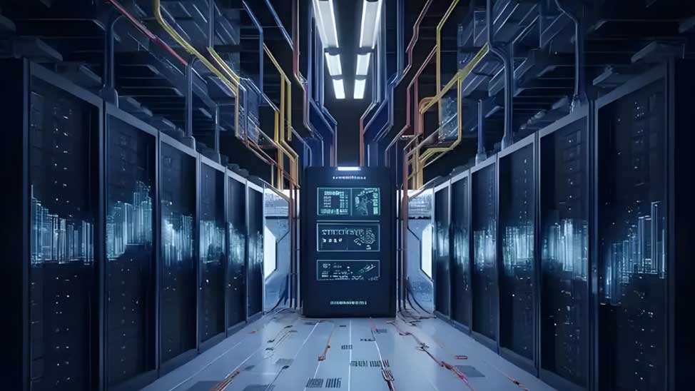
Campus fabric architecture replaces the traditional three-tier hierarchy with a flat, scalable spine-leaf topology
1. What Is Campus Fabric Architecture?
Campus fabric architecture is a network design paradigm that unifies management, security, and forwarding into a single logical entity. Instead of the traditional device-by-device configuration model, a fabric abstracts complexity through intent-based automation, where policies are defined once and enforced across the entire campus in minutes rather than hours.
At its core, a campus fabric decouples the underlay (physical IP network providing Layer 3 connectivity) from the overlay (virtual topology using VXLAN tunnels for Layer 2 extension). This separation enables independent scaling, simplified operations, and consistent policy enforcement regardless of where endpoints physically connect.
The key characteristics that define a campus fabric include:
- Flat topology: Spine-leaf or IP-Clos design replaces the multi-tier hierarchy, reducing latency to two hops between any two endpoints
- Control-plane learning: EVPN via BGP distributes MAC and IP reachability, eliminating flood-and-learn behavior
- Overlay segmentation: VXLAN Network Identifiers (VNIs) support up to 16 million segments versus the 4,094 VLAN limit
- Intent-based automation: Changes are defined once and pushed to thousands of devices simultaneously
- Location-agnostic connectivity: Endpoints receive consistent policies regardless of physical port or building
2. Traditional Three-Tier vs. Campus Fabric: Core Differences
The traditional campus network follows a three-tier model: access switches connect end devices, aggregation switches bundle VLANs and provide routing, and core switches interconnect buildings. This design worked when traffic flowed predominantly north-south (client to server), but modern campus traffic patterns are overwhelmingly east-west, driven by collaboration tools, IoT, and localized cloud services.
| Feature | Traditional Three-Tier | Campus Fabric |
|---|---|---|
| Topology | Access, Aggregation, Core hierarchy | Flat spine-leaf (IP-Clos) |
| Loop Prevention | Spanning Tree Protocol (blocks links) | Layer 3 routing (all links active via ECMP) |
| Segmentation Limit | 4,094 VLANs | 16 million VXLAN VNIs |
| MAC Learning | Flood-and-learn (data plane) | Control-plane via BGP EVPN |
| Traffic Path | Multi-hop through aggregation and core | Two hops (leaf-spine-leaf) |
| Scaling Method | Larger aggregation switches, more VLANs | Add leaf or spine switches linearly |
| Convergence Time | Seconds to minutes (STP reconvergence) | Sub-100ms (BFD with BGP fast-failover) |
| Management | Device-by-device CLI configuration | Intent-based, fabric-wide automation |
| Policy Enforcement | VLAN and ACL per switch | Identity-based microsegmentation |
The most damaging limitation of the three-tier model is Spanning Tree Protocol. STP blocks redundant links to prevent loops, meaning up to 50% of available bandwidth sits idle. In a fabric, all links are active using Equal-Cost Multi-Path (ECMP) routing, maximizing bandwidth utilization and providing automatic failover without protocol reconvergence delays.
Fragmented network construction also drives costs. Independent networks for office, production, security, and IoT systems lead to more than 40% increases in both CAPEX and OPEX, with mean time to repair (MTTR) exceeding 4 hours. A unified fabric consolidates these silos into a single, manageable infrastructure. For organizations questioning whether their current approach can scale, the limitations of traditional networks become apparent quickly as device counts grow.
3. Key Technologies: EVPN, VXLAN, and IP-Clos
3.1 VXLAN: The Data Plane Overlay
VXLAN (Virtual Extensible LAN) is a MAC-in-UDP encapsulation protocol that tunnels Layer 2 Ethernet frames over a Layer 3 network. Each virtual network is identified by a 24-bit VXLAN Network Identifier (VNI), providing an address space of 16 million segments. This directly solves the 4,094 VLAN limitation that constrains large campus deployments.
VXLAN Tunnel Endpoints (VTEPs), typically residing on leaf or access-layer switches, perform the encapsulation and decapsulation. The underlay network sees only IP packets, meaning the physical infrastructure requires no special configuration to support Layer 2 extension across buildings or campuses.
3.2 EVPN: The Control Plane
EVPN (Ethernet VPN) is a standards-based control plane (RFC 7432) that uses BGP extensions to distribute MAC address and IP reachability information between VTEPs. This replaces the inefficient flood-and-learn mechanism used in traditional Layer 2 networks, where unknown unicast frames are flooded across the entire VLAN.
With EVPN, MAC addresses are learned in the control plane and advertised via BGP route types. This means switches know exactly which VTEP owns each MAC address without flooding. The result is dramatically reduced broadcast traffic, faster convergence, and the ability to scale to tens of thousands of endpoints without degrading performance.
EVPN control-plane learning eliminates flood-and-learn behavior, improving scalability and reducing broadcast traffic
3.3 IP-Clos Topology
The IP-Clos (spine-leaf) topology is the physical foundation of a campus fabric. Spine switches form the high-speed backbone, and every leaf switch connects to every spine. Critially, leaves connect only to spines and spines connect only to leaves, creating a non-blocking full-mesh design.
This architecture provides several structural advantages:
- Predictable latency: Every leaf is exactly two hops from any other leaf, creating uniform performance
- Linear scaling: Add leaf switches for more access ports, add spine switches for more inter-leaf bandwidth
- Non-blocking fabric: ECMP distributes traffic across all available spine links
- Inherent redundancy: If a spine fails, remaining spines maintain connectivity with automatic path redistribution
4. Scalability Benefits: How Fabric Scales Beyond VLAN Limits
The scalability of a campus fabric stems from a fundamental architectural difference: in a traditional network, core switches must learn every endpoint MAC address. In a fabric, core (spine) switches only learn the addresses of access-layer (leaf) switches. This reduces the MAC table size by orders of magnitude, enabling predictable growth as branches, users, and devices are added.
Consider a campus with 10,000 endpoints spread across 50 access switches. A traditional core switch must maintain 10,000 MAC entries. In an IP-Clos fabric, the spine switches need only 50 entries, one per leaf. The leaves handle endpoint MAC learning locally, and EVPN distributes only the necessary reachability information upstream.
Scalability Comparison at a Glance
| Scaling Dimension | Traditional Network | Campus Fabric |
|---|---|---|
| Max Segments | 4,094 VLANs | 16 million VNIs |
| Core MAC Table | Every endpoint MAC | Only leaf switch addresses |
| Active Links | 50% (STP blocks half) | 100% (ECMP uses all) |
| Adding Capacity | Replace core/aggregation switches | Insert new leaf or spine switches |
| Broadcast Traffic | Flooded across VLANs | ARP suppression via EVPN |
| Multi-Tenancy | VRF + VLAN (complex) | VNI per tenant (native) |
The 16-million VNI address space is not just theoretical. Multi-tenant campuses, such as university research parks or multi-building corporate campuses, routinely exhaust VLAN limits when each tenant requires isolated network segments. VXLAN eliminates this constraint, and the EVPN control plane ensures that adding new tenants or segments requires no changes to the physical underlay.
For organizations planning network expansion, understanding structured cabling for campus networks is essential, as the physical infrastructure must support the increased fiber density that spine-leaf topologies demand.
5. Security and Microsegmentation in Campus Fabrics
Traditional campus security relies on VLAN-based segmentation and access control lists (ACLs) configured on individual switches. This model is coarse, static, and difficult to maintain as policies scale. A single policy change might require touching hundreds of switches, and VLAN boundaries do not follow users as they move between buildings.
Campus fabrics solve this through a layered security model:
5.1 Macro-Segmentation with VRF
Virtual Routing and Forwarding (VRF) instances provide network-level isolation at the routing layer. Each VRF maintains its own routing table, meaning traffic from one VRF cannot reach another without explicit route leaking or a firewall. This is ideal for separating guest networks, IoT segments, and production traffic.
5.2 Micro-Segmentation with Identity-Based Policies
Microsegmentation applies access controls at the individual device or workload level rather than the VLAN level. Technologies like Cisco Security Group Tags (SGT) and Juniper Group-Based Policies (GBP) assign identity labels to endpoints. Policies are then defined between identity groups, not IP subnets, and they follow endpoints regardless of physical location.
For example, an IoT security camera connecting in Building A receives the same access restrictions as the same camera model connecting in Building C. The policy is tied to the device identity, not the switch port. This enables true zero-trust architectures where every connection is verified and least-privilege access is enforced automatically.
Real-World Example: University of Maryland
The University of Maryland deployed a campus fabric with HPE Aruba Networking across its 1,300-acre campus, supporting 80,000 endpoints with 19,000 wireless APs. Using dynamic segmentation, the university reduced legacy VLAN by approximately 90%, freeing three full-time engineers from manual VLAN administration to focus on higher-value projects. AI-powered monitoring proactively identified issues before users reported them, saving four-hour round trips to distant campus locations.
5.3 Zero Trust Integration
Modern campus fabrics integrate with identity providers and Network Access Control (NAC) systems to enforce zero-trust principles:
- 802.1X with EAP-TLS: Certificate-based authentication for every endpoint connection
- Dynamic VLAN/VNI assignment: Endpoints are placed into the correct segment based on identity, not port configuration
- Continuous posture checks: Integration with MDM/UEM platforms ensures device compliance before granting access
- MACsec encryption: Layer 2 encryption on inter-switch links (IEEE 802.1AE) protects against physical tap attacks
For environments with specific EMI concerns, such as manufacturing floors or healthcare facilities, combining fabric security with proper EMI/RFI interference solutions ensures both logical and physical layer protection.
6. Deployment Models: Cloud, On-Prem, and Programmable
Campus fabrics can be managed through three primary models, each offering different levels of control, automation, and customization:
| Model | Management | Best For | Key Advantage |
|---|---|---|---|
| Cloud-Managed Fabric | Cloud dashboard (e.g., Meraki, Mist) | Organizations seeking agility and simplified operations | Turnkey deployment, AI-driven insights, zero-touch provisioning |
| On-Premises Fabric | Local controller (e.g., Cisco Catalyst Center) | Regulated environments requiring data sovereignty | Deep customization, full operational autonomy |
| Programmable Fabric | CLI + automation scripts (Ansible, Terraform) | Highly distributed, specialized environments | Maximum flexibility, infrastructure-as-code |
All three models share the same underlying technologies (EVPN, VXLAN, IP-Clos) and can run on the same hardware. The difference lies in the management abstraction layer. Cloud-managed fabrics, such as those built on Juniper Mist Wired Assurance, add AI-powered operations through the Marvis Virtual Network Assistant, which provides anomaly detection, trend analysis, and proactive remediation.
Cloud-managed fabrics also benefit from rapid feature delivery. Recent additions to cloud management platforms include BGP, VRF, In-Service Software Upgrade (ISSU), and VRRP support, enabling enterprise-grade fabric capabilities through a simplified cloud interface.
7. Real-World Implementation and Cabling Considerations
The physical infrastructure underlying a campus fabric is as critical as the overlay protocols. A spine-leaf topology requires significantly more parallel fiber links than a three-tier design, because every leaf connects to every spine. This means the cabling plant must be planned for density, redundancy, and future growth.
Campus fabric spine-leaf topology demands high-density fiber cabling between every spine and leaf switch pair
7.1 Fiber Infrastructure for Spine-Leaf Interconnects
Spine-to-leaf links typically run at 10G, 25G, 40G, or 100G, depending on campus size and bandwidth requirements. For distances under 300 meters, OM4 multimode fiber with MPO-12 connectors is cost-effective. For inter-building runs exceeding 300 meters, OS2 singlemode fiber with LC duplex connectors is mandatory. Pre-terminated MPO trunk cables accelerate deployment and ensure consistent performance.
7.2 Copper Cabling for Access Layer
The access layer connects endpoints, Wi-Fi APs, and IoT devices. With Wi-Fi 6E and Wi-Fi 7 APs requiring multi-gigabit backhaul (2.5G, 5G, or 10G) and up to 90W PoE (IEEE 802.3bt Type 4), Cat6a is the minimum recommended copper grade for new campus deployments. Cat6 can support 10G up to 55 meters in controlled environments but suffers from alien crosstalk in bundled runs, making it unsuitable for high-density PoE deployments.
For organizations planning AP upgrades, consider NBASE-T multi-gigabit upgrade paths to ensure existing cabling can support next-generation wireless speeds.
7.3 Migration Strategy: Phased, Not Forklift
Standard Migration Approach
Migrating from a three-tier campus to a fabric does not require a full rip-and-replace. The proven approach follows these phases:
- Phase 1 (Months 1-3): Deploy new spine-leaf fabric alongside the existing network. The legacy core temporarily acts as a border leaf, connecting old and new domains via BGP or static routing.
- Phase 2 (Months 3-9): Migrate buildings or VLAN groups progressively. Start with non-critical segments (guest networks, IoT pilot zones) to validate fabric behavior.
- Phase 3 (Months 9-18): Migrate production segments with rollback capability. Use EVPN multihoming to enable dual-homing during transition for zero-downtime cutover.
- Phase 4 (Month 18+): Decommission legacy aggregation and core switches once all traffic flows through the fabric.
Existing access-layer switches can often be retained, especially if they support VXLAN-VTEP functionality. The EVPN-VXLAN overlay is vendor-agnostic, meaning multi-vendor fabrics are feasible with standards-compliant equipment.
Proper cable management becomes even more critical in a fabric deployment due to increased fiber density. Following patch panel cable management best practices ensures maintainability and reduces the risk of human error during fiber moves, adds, and changes.
8. Future-Proofing: AI Operations and Wi-Fi 7 Readiness
Campus fabric architecture is not just a fix for today's limitations; it is the foundation for the next decade of network evolution. Two trends are driving this: AI-powered network operations and the transition to Wi-Fi 7.
8.1 AI-Driven Network Operations
AI and machine learning are transforming how campus networks are managed. Platforms like Juniper Mist and Cisco Catalyst Center embed AI engines that provide:
- Proactive anomaly detection: Identify performance degradation before users report issues
- Automated root-cause analysis: Correlate events across wired and wireless domains to pinpoint failures
- Self-healing infrastructure: Automatically adjust power, channel, and routing parameters to resolve issues
- Predictive capacity planning: Forecast bandwidth and port utilization to guide hardware refresh cycles
These AI capabilities depend on the rich telemetry and centralized control that fabric architectures provide. Traditional device-by-device networks lack the visibility and programmability needed for AI-driven operations.
8.2 Wi-Fi 7 and Multi-Gigabit Access
Wi-Fi 7 (802.11be) delivers theoretical speeds up to 46 Gbps and introduces 320 MHz channel widths, MLO (Multi-Link Operation), and 4K-QAM. Real-world goodput is expected to reach 1.5 to 2 Gbps per client at 160-320 MHz. This demands 10G backhaul to each AP, which in turn requires Cat6a cabling and multi-gigabit switch ports.
According to IDC, Wi-Fi 7's market share is expected to grow more than fourfold over the next five years, reaching over 63% by 2029. Campus fabrics are inherently ready for this transition because the spine-leaf underlay provides abundant bandwidth, and EVPN-VXLAN overlay scales to accommodate the increased segmentation needs of thousands of APs.
AI-driven network operations and Wi-Fi 7 readiness are native to campus fabric architectures
8.3 The 10G Campus Era
By 2030, the total number of global connections is projected to exceed 200 billion, with 10 Gbps connectivity becoming the norm. Campus networks must evolve from 1G access to 10G access to support this density. Fabric architectures, with their non-blocking ECMP design and scalable spine-leaf topology, are the only model that can accommodate this growth without architectural rework.
For enterprises evaluating their long-term infrastructure strategy, understanding the evolution of structured network cabling provides context for how physical infrastructure must adapt to support fabric-scale connectivity.
Campus Fabric Readiness Checklist
- Inventory current VLAN count and identify segments approaching the 4,094 limit
- Audit fiber infrastructure between buildings for spine-leaf density requirements
- Verify access-layer switches support EVPN-VXLAN or plan for phased replacement
- Assess PoE power budget for Wi-Fi 6E/7 APs and IoT device density
- Identify a pilot building or segment for initial fabric deployment
- Evaluate cloud-managed versus on-premises management based on compliance needs
- Plan for 10G access-layer uplinks and Cat6a cabling for all new AP installations
- Engage with a cabling partner for pre-terminated MPO trunk cable specifications
Key Questions (FAQ)
Q1: What is campus fabric architecture?
Campus fabric architecture is a network design model that replaces the traditional three-tier (access-aggregation-core) hierarchy with a flat, spine-leaf or IP-Clos topology. It uses EVPN as the control plane and VXLAN as the data plane overlay to provide scalable segmentation, eliminates Spanning Tree Protocol, and abstracts network complexity into a single logical entity managed through intent-based automation.
Q2: How does campus fabric differ from traditional three-tier network design?
Traditional three-tier designs rely on Spanning Tree Protocol (which blocks redundant links), are limited to 4,094 VLANs, and use flood-and-learn MAC discovery. Campus fabric uses Layer 3 routing in the underlay (eliminating STP), EVPN control-plane MAC learning via BGP (eliminating flooding), and VXLAN overlays supporting up to 16 million segments. The fabric also enables any-to-any connectivity in two hops instead of traversing aggregation and core layers.
Q3: What are EVPN and VXLAN in a campus fabric?
VXLAN (Virtual Extensible LAN) is the data-plane encapsulation protocol that tunnels Layer 2 Ethernet frames over Layer 3 UDP, enabling Layer 2 extension across the fabric. EVPN (Ethernet VPN) is the BGP-based control plane that distributes MAC and IP reachability information between VXLAN Tunnel Endpoints (VTEPs), replacing the inefficient flood-and-learn mechanism. Together, they enable scalable multi-tenancy, workload mobility, and microsegmentation.
Q4: How many devices can a campus fabric support?
Campus fabric architectures scale predictably because core (spine) switches only learn access-layer switch addresses rather than individual endpoint MAC addresses. A well-designed IP-Clos fabric can support tens of thousands of endpoints across multiple buildings. The 16-million VNI address space far exceeds the 4,094 VLAN limit, and adding capacity is as simple as inserting new leaf or spine switches without rearchitecting the fabric.
Q5: Does campus fabric architecture eliminate Spanning Tree Protocol?
Yes, campus fabric eliminates STP in the core and inter-switch links by using Layer 3 routed connections between spines and leaves. All links are active using Equal-Cost Multi-Path (ECMP) routing, meaning no bandwidth is wasted on blocked ports. STP may still run on server-facing access ports within individual VLANs, but EVPN multihoming (ESI-LAG) handles dual-homed server redundancy without STP.
Q6: What is microsegmentation in a campus fabric?
Microsegmentation is a security model that applies access policies at the workload or device level rather than the VLAN level. In campus fabrics, technologies like Cisco Security Group Tags (SGT) or Juniper Group-Based Policies (GBP) assign identity-based policies that follow endpoints regardless of physical location. This enables zero-trust architectures where IoT devices, user groups, and servers are isolated even within the same broadcast domain.
Q7: Can I migrate from a traditional campus network to fabric without a full rip-and-replace?
Yes. The standard migration approach deploys a new fabric overlay alongside the existing three-tier network, then progressively migrates buildings or VLANs. The legacy core temporarily acts as a border leaf connecting old and new fabrics via BGP or static routing. Full cutover typically takes 6 to 18 months for medium-sized enterprises, and existing access-layer switches can often be retained since the EVPN-VXLAN overlay is vendor-agnostic.
Q8: What cabling infrastructure does a campus fabric require?
Campus fabrics require robust physical cabling: fiber (OS2 singlemode or OM4 multimode) for spine-to-leaf interconnects, Cat6a or Cat6 copper for access-layer uplinks and Wi-Fi 6E/7 APs with PoE++, and high-density patch panels for cable management. The flat topology means more parallel fiber links between spines and leaves compared to a three-tier design, so pre-terminated MPO trunk cables and structured cabling best practices are essential.
About AMPCOM Campus Network Solutions
AMPCOM supplies the complete physical infrastructure that campus fabric architectures demand:
- OS2 Singlemode Fiber: ITU-T G.652.D compliant, LC/SC/MPO connectors, for inter-building spine-leaf links exceeding 300 meters
- OM4 Multimode Fiber: TIA-492AAAE compliant, laser-optimized, MPO-12 trunk assemblies for intra-building spine-leaf interconnects
- Cat6a Copper Cabling: 23 AWG, shielded and unshielded options, for multi-gigabit Wi-Fi 6E/7 AP backhaul and high-power PoE++ (90W) deployments
- High-Density Patch Panels: 1U and 0.5U configurations, 24/48-port, for organized fiber and copper management in campus MDF/IDF rooms
- Pre-Terminated Trunk Cables: MPO-to-MPO and MPO-to-LC fan-out assemblies for rapid spine-leaf deployment with guaranteed performance
- Custom Solutions: Tailored cable lengths, connector types, and jacket materials for unique campus environments
Related Articles
- What Is Structured Cabling for SMB Campus Networks — Foundational cabling principles that every campus fabric deployment builds upon
- The Evolution and Future of Structured Network Cabling — How cabling standards are adapting to fabric-scale connectivity demands
- Patch Panel Cable Management: Complete Guide for Enterprise Networks — Best practices for managing high-density fiber in spine-leaf topologies
- Limitations of Traditional Networks — Why three-tier architectures fail at modern campus scale
- NBASE-T Multi-Gigabit: Real-World Limits and Upgrade Paths — Preparing access-layer cabling for Wi-Fi 7 multi-gigabit AP backhaul
- EMI/RFI Interference Solutions for Manufacturing and Healthcare — Physical-layer protection strategies for campus fabric edge environments

AMPCOM Technical Team
Industry experts with 17+ years in enterprise network infrastructure and structured cabling systems
Planning a campus fabric deployment?
Our technical team provides free consultation on fiber trunk specifications, Cat6a cabling, and patch panel configurations for spine-leaf campus architectures.
Get Free Expert Consultation

