
400G Spine-Leaf Design Guide: Scaling AI and HPC Clusters
Published:Executive Summary: GPU training stalls on wrong fabric. Master 400G spine-leaf design: topology choices, OSFP vs QSFP-DD, lossless Ethernet, and cabling strategies for AI scale.
This guide walks network architects and IT decision-makers through every layer of a production-grade 400G spine-leaf fabric — from topology math and transceiver selection to lossless Ethernet tuning, power planning, and phased deployment strategies backed by 2025 industry data.
Quick Navigation
- 1 The 400G Imperative for AI and HPC
- 2 Spine-Leaf Architecture Fundamentals
- 3 400G Transceivers: OSFP vs QSFP-DD
- 4 Cabling Strategy for 400G Fabrics
- 5 Lossless Ethernet and Congestion Management
- 6 Power, Thermal, and Rack Planning
- 7 Deployment Roadmap and Best Practices
- 8 Future-Proofing: 400G to 800G and Beyond
- 9 Key Questions (FAQ)

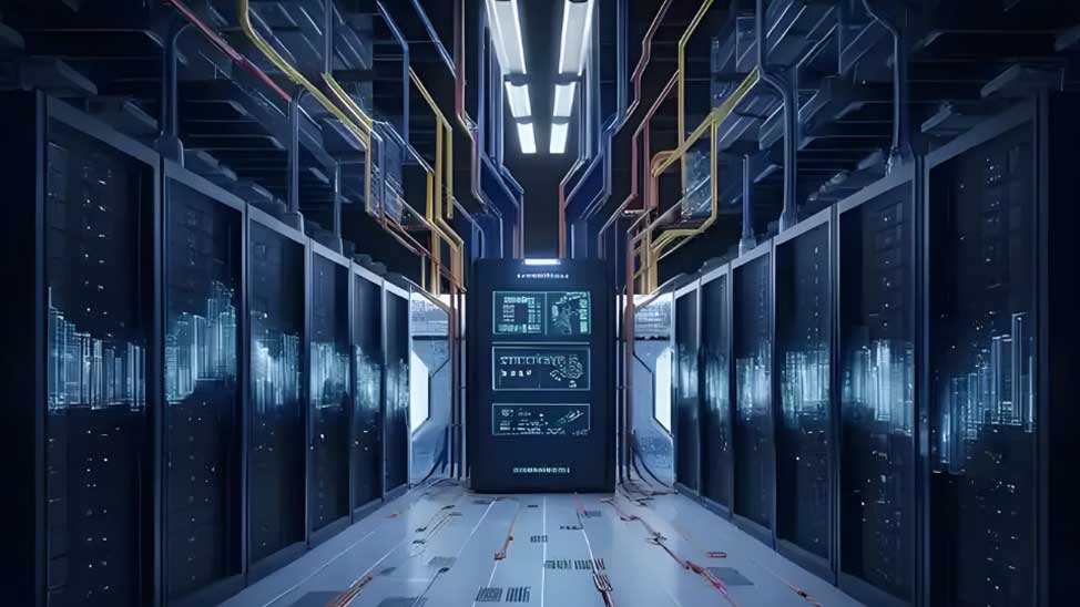
A two-tier 400G spine-leaf fabric — every leaf connects to every spine, ensuring predictable two-hop latency for GPU-to-GPU communication
1. The 400G Imperative for AI and HPC
The economics of AI training have fundamentally changed network architecture requirements. Frontier model training runs now routinely deploy clusters exceeding 50,000 to 100,000 GPUs, each demanding sustained 400Gbps bandwidth for all-to-all collective communication. When any packet drops in these collectives, retransmission storms cascade across the entire job, reducing effective GPU utilization by 15-40% and extending training wall-clock times by days or weeks.
The market response has been explosive. Global Ethernet switch sales reached $14.7 billion in Q3 2025, a 35.2% year-over-year increase, with the data center segment growing 62%. High-speed ports (200G+) accounted for 27.9 million of the 73.5 million total ports shipped that quarter — all destined for data center spine-leaf fabrics. By 2025, spine-leaf architecture penetration in data centers surpassed 67%, displacing the legacy three-tier core-aggregation-access model.
| Metric | 2022 | 2025 | Trend |
|---|---|---|---|
| Ethernet share of new GPU cluster deployments | 41% | 62% | Rapid growth |
| 400G/800G switch port shipments | ~4M | 10M+ | 2.5x growth |
| Spine-leaf data center penetration | ~45% | 67%+ | Dominant architecture |
| AI lossless Ethernet fabric market | $1.8B | $6.2B | 18.6% CAGR through 2034 |
The message is clear: 400G spine-leaf is no longer a future architecture — it is the present standard for any organization building AI or HPC infrastructure at scale. Understanding its design principles is essential before committing capital. For broader context on how AI workloads reshape cabling requirements, see our guide on AI infrastructure data center cabling requirements.
2. Spine-Leaf Architecture Fundamentals
2.1 Topology Design
Spine-leaf is a two-tier Clos network where every leaf switch connects to every spine switch using equal-capacity links. This design guarantees that any two endpoints communicate through exactly two hops — leaf to spine to leaf — providing highly predictable and consistent latency regardless of traffic patterns.
| Characteristic | Three-Tier (Legacy) | Spine-Leaf |
|---|---|---|
| Hop count (server to server) | 3-7 hops (variable) | 2 hops (fixed) |
| Latency | Higher, unpredictable | Sub-microsecond, predictable |
| Traffic optimization | North-south (internet-facing) | East-west (server-to-server) |
| Scalability | Difficult, requires redesign | Add spine switches horizontally |
| Oversubscription | Common at aggregation tier | 1:1 non-blocking achievable |
| Best for | Traditional enterprise apps | AI, HPC, cloud-scale workloads |
2.2 Oversubscription and Bandwidth Planning
In a typical 2025 AI cluster deployment, a leaf switch might offer 64 x 400GbE downlink ports for server connectivity and 8 x 400GbE uplink ports for spine connectivity, while a spine switch aggregates 32 x 400GbE or 16 x 800GbE uplinks, providing up to 12.8 Tbps of non-blocking switching capacity per spine node. The leaf-to-spine ratio typically ranges from 4:1 to 8:1 depending on oversubscription requirements.
For organizations also managing traditional Fibre Channel environments alongside Ethernet fabrics, understanding the differences between Ethernet cards and Fibre Channel cards is essential for hybrid infrastructure planning.
2.3 Scale Calculations
A single-spine, two-tier fabric with 64-radix spine switches can support 2,048 server ports at 3:1 oversubscription. For larger AI clusters, multi-spine designs scale linearly. The HPE Slingshot 400 platform, for example, supports dragonfly topologies with over 260,000 endpoints in a unified cluster — but for most enterprises, a well-designed spine-leaf fabric handles AI workloads up to approximately 16,000 GPUs cost-effectively.
3. 400G Transceivers: OSFP vs QSFP-DD
The choice between OSFP and QSFP-DD form factors is one of the most consequential decisions in 400G spine-leaf design — it determines your migration path to 800G and beyond, thermal headroom, and per-port economics.
OSFP vs QSFP-DD — the form factor choice determines your 800G migration path and thermal headroom
| Parameter | OSFP | QSFP-DD |
|---|---|---|
| Dimensions (W x D) | 22.5mm x 38mm | 18.4mm x 89mm |
| Electrical channels | 8 lanes | 8 lanes |
| 400G implementation | 8 x 56G PAM4 | 8 x 56G PAM4 |
| 800G support | Native (8 x 112G PAM4) | Supported, thermal limits at 25W+ |
| 1.6T path (OSFP1600) | Same form factor, software upgrade | Not supported |
| Max module power | 25W+ (800G DR8) | ~20W (thermal constrained) |
| Backward compatibility | No (new cage required) | Yes (QSFP28/QSFP+) |
| 2025 market share (800G) | 46% | 37.6% |
| Best for | New AI builds, 800G migration | Upgrades from 100G/200G |
OSFP's larger physical footprint provides superior thermal management — critical because 800G DR8 modules can draw 18-25W each. A 32-port 800G switch with fully loaded OSFP modules consumes 1,200-1,500W on optics alone. QSFP-DD remains the volume leader for 400G deployments due to its backward compatibility and established ecosystem, holding 37.6% of the data center transceiver market in 2025. For organizations planning 800G migration within 2-3 years, OSFP is the strategic choice.
For more on transceiver lifecycle management, including when to replace aging modules, see our guide on optical transceiver lifespan and replacement.
4. Cabling Strategy for 400G Fabrics
Cable selection in a 400G spine-leaf fabric directly impacts cost, reliability, and future migration paths. The primary decision factors are distance, density, and whether you plan to migrate to 800G.
| Distance | Cable Type | Connector | Power | Typical Use |
|---|---|---|---|---|
| 0.8 - 3m | Passive DAC | QSFP-DD/OSFP | 0.5W | Intra-rack GPU to leaf |
| 1.6 - 5m | Active Electrical (AEC) | QSFP-DD/OSFP | 11W | Intra-row leaf to leaf |
| 5 - 100m | Active Optical (AOC) | MPO-12/MPO-16 | 16W | Inter-row leaf to spine |
| 100 - 500m | 400G DR4 transceiver + OS2 | MPO-12 APC | 15-18W | Spine-leaf interconnect |
| 500m - 2km | 400G FR4 transceiver + OS2 | LC duplex APC | 15-18W | Cross-fabric connections |
| 2km - 10km | 400G LR4 transceiver + OS2 | LC duplex APC | 15-18W | Campus DCI |
4.1 Fiber Type Selection
For 400G spine-leaf fabrics, OS2 singlemode fiber (ITU-T G.652.D) is the recommended choice for all spine-leaf links. While OM4/OM5 multimode can support 400G-SR8 at 100m, it faces hard distance limits at 800G and is incompatible with 1.6T roadmaps. The cost difference between OM4 and OS2 is negligible compared to total deployment cost, and OS2 provides future-proofing for at least two technology generations.
For organizations choosing between fiber types, our fiber optic cable types guide and single-mode vs multimode comparison provide detailed decision frameworks.
4.2 Connector and Polishing Requirements
400G OSFP SR8 and DR8 modules use MPO-16 connectors (16 fibers in a single row). Singlemode applications require APC polishing to prevent reflection-induced bit errors. A critical field statistic: 70% of DR4 link failures are caused by connector contamination, not module defects. Always inspect connectors with a 200x-400x microscope before insertion and use dedicated multi-fiber cleaning tools for MPO interfaces.
For structured cabling standards compliance, refer to our guide on TIA-568 vs ISO/IEC 11801 standards. Proper cable color coding and labeling is equally critical in high-density 400G environments where hundreds of identical-looking fiber runs converge at patch panels.
4.3 Breakout Cable Strategy
During migration phases, breakout cables enable mixing speeds across the fabric. The 800G-to-2x400G breakout is the most common — it allows a new 800G spine switch port to connect to two existing 400G leaf switches. This strategy extends the life of 400G leaf switches while upgrading the spine layer, reducing migration CAPEX by up to 40% compared to a full forklift upgrade.
For understanding how DAC and AOC cables fit into this strategy, see our DAC cable types and use cases guide and the AOC vs DAC buyer's guide.
5. Lossless Ethernet and Congestion Management
The defining requirement for AI-grade Ethernet fabrics is lossless transport — zero packet drop during GPU collective communication operations such as all-reduce, all-gather, and ring-allreduce. Without it, RDMA retransmission storms reduce effective GPU utilization by 15-40%.
5.1 The Three Pillars of Lossless Ethernet
| Mechanism | Function | Configuration |
|---|---|---|
| PFC (Priority Flow Control) | Pause traffic on specific priority classes to prevent buffer overflow | Enable on RoCEv2 traffic class (typically priority 3) |
| ECN (Explicit Congestion Notification) | Mark packets when switch buffer thresholds are exceeded | Set min/max thresholds at 150KB/1.5MB per port |
| DCQCN | Dynamically reduce sender rate based on ECN feedback | Tune timer, alpha update rate, and fast-recovery parameters |
When properly configured, DCQCN maintains RoCEv2 goodput within 5-10% of line rate during sustained training workloads across clusters of 1,000 to 16,000 GPUs. The PFC/DCQCN protocol segment accounted for 28.1% of the AI lossless Ethernet fabric market in 2025, growing at 17.9% CAGR.
5.2 RoCEv2 vs InfiniBand
| Parameter | RoCEv2 (Ethernet) | InfiniBand |
|---|---|---|
| Latency (small messages) | 1.5-2.5 microseconds at 400G | 0.6-1.0 microseconds at HDR 200G |
| Lossless transport | Requires PFC + ECN + DCQCN tuning | Native (credit-based flow control) |
| Per-port cost | Baseline | 35-50% higher |
| Ecosystem openness | Multi-vendor, open standards | Vendor-locked (NVIDIA/Mellanox) |
| 2025 hyperscale share | 62% of new deployments | 38% |
The cost advantage is decisive at scale. A 1,024-GPU cluster requires approximately 128 x 800G leaf ports, and the 35-50% per-port cost difference between Ethernet and InfiniBand translates to millions of dollars in CAPEX. For organizations with existing Fibre Channel investments, understanding the Fibre Channel networking landscape helps evaluate hybrid strategies.
5.3 FEC Configuration
At 400G and above, Forward Error Correction is mandatory. The standard is RS-FEC (544,514), which corrects up to 15 bit errors per 544-bit block. Acceptable pre-FEC bit error rate is 10^-4 to 10^-5; post-FEC BER should be effectively zero. FEC must be configured identically on both ends of a link — mismatched FEC settings are a common cause of link initialization failures.
6. Power, Thermal, and Rack Planning
400G and 800G networking introduces power density challenges that traditional data center designs cannot accommodate. Without proper planning, thermal throttling will degrade switch performance and shorten module lifespans.
| Component | Power per Unit | Per-Rack Total |
|---|---|---|
| 51.2T switch baseboard | 400-600W | 1,600-2,400W (4 switches) |
| 400G OSFP modules (32 per switch) | 12-18W each | 1,536-2,304W (4 switches) |
| 800G OSFP modules (32 per switch) | 18-25W each | 2,304-3,200W (4 switches) |
| Network total per rack | — | 6.4-8.4kW (400G) / 8.0-10.6kW (800G) |
| Recommended rack PDU capacity | — | 12-15kW (with compute headroom) |
For organizations managing cable infrastructure in high-density environments, proper patch panel cable management and patch cord length planning are critical — airflow blockages from poorly routed cables can raise switch intake temperatures by 5-10 degrees C.
7. Deployment Roadmap and Best Practices
A successful 400G spine-leaf deployment follows a phased approach that minimizes disruption to existing workloads while validating performance at each stage.
A phased deployment roadmap minimizes risk and validates performance at each stage of 400G migration
7.1 Phase 1 — Spine Layer Deployment (3-6 months)
Spine-First Strategy
- Deploy new 800G-capable spine switches in parallel with existing infrastructure
- Use 800G-to-2x400G breakout cables to connect existing 400G leaf switches to new spine ports
- Validate each link with 24-48 hour BER monitoring and optical power verification
- Configure ECMP, BGP EVPN, and initial PFC/ECN settings
- Migrate non-critical workloads first to validate fabric stability
7.2 Phase 2 — Leaf Switch Migration (2-4 months)
Rack-by-Rack Cutover
- Migrate leaf switches in groups of 8-16 ports at a time
- Maintain dual-homed server connections during cutover to preserve redundancy
- Notify application teams 48-72 hours in advance of each migration window
- Verify RoCEv2 performance with synthetic all-reduce benchmarks after each cutover
- Replace DAC/AOC cables with native 400G transceiver connections where distance allows
7.3 Phase 3 — Native High-Speed Operation (1-2 months)
Optimization and Validation
- Remove breakout cables and install direct OSFP-OSFP connections
- Spine port effective capacity doubles (from 400G to 800G per port)
- Fine-tune buffer settings, ECN thresholds, and DCQCN parameters
- Run full performance validation: throughput, latency, failover, and RoCEv2 goodput
- Deploy interconnect topology optimization for east-west traffic patterns
Pre-Deployment Checklist
- Verify all switch, NIC, transceiver, and cable PIDs against compatibility matrices
- Confirm firmware and driver versions across all components
- Validate rack power capacity (12-15kW minimum for 400G, 15-20kW for 800G)
- Ensure cooling capacity matches switch thermal output (300-400 CFM/kW)
- Plan fiber pathways and verify MPO polarity consistency (Method A recommended)
- Prepare rollback procedures for each migration phase
- Stock spare transceivers and cables (minimum 5% of deployment quantity)
8. Future-Proofing: 400G to 800G and Beyond
The 400G spine-leaf you deploy today should be designed with a clear migration path to 800G and 1.6T. The 800G optical transceiver market reached $4.85 billion in 2025 and is projected to hit $42.8 billion by 2035 (24.1% CAGR). By 2026, 800G will account for an estimated 18% of new AI fabric port shipments, rising to over 45% by 2028.
| Technology | Timeline | Key Specification | Impact on 400G Fabric |
|---|---|---|---|
| 800G (8x100G PAM4) | Volume deployment 2025-2026 | 18-25W per module, OSFP | 2x capacity per spine port via breakout |
| 1.6T (OSFP1600) | Early adopter 2027 | 8x200G, up to 33W, same form factor | 4x capacity, software-upgradable cages |
| LPO (Linear Pluggable Optics) | 2026-2027 | 30-50% lower power, no DSP | Reduces switch thermal load significantly |
| CPO (Co-Packaged Optics) | 2027-2028 | Optics in switch ASIC package | 40-50% power reduction, eliminates faceplate cables |
For organizations planning around NVIDIA's hardware refresh cycles, our analysis of NVIDIA's 2026 data center roadmap provides forward-looking infrastructure planning guidance. Understanding AI frontend vs backend network design differences is also critical when planning fabric topology for mixed AI workloads.
Key Questions (FAQ)
Q1: What is a spine-leaf architecture and why is it used for AI and HPC?
Spine-leaf is a two-tier Clos network topology where every leaf switch connects to every spine switch, providing predictable two-hop latency between any endpoints. It is used for AI and HPC because it optimizes east-west traffic (server-to-server communication), supports non-blocking bandwidth, and scales horizontally by adding spine switches without redesigning the fabric. In 2025, spine-leaf held 54.3% of the fabric type market for AI clusters.
Q2: What is the difference between OSFP and QSFP-DD for 400G networks?
OSFP (22.5mm x 38mm) supports higher power modules up to 25W+ and provides a native path to 800G and 1.6T via OSFP1600 — the same physical form factor with a software upgrade. QSFP-DD is smaller, backward compatible with QSFP28/QSFP+, and dominates the 400G market with 37.6% share. Choose OSFP for new AI infrastructure targeting 800G+ migration within 2-3 years; choose QSFP-DD when upgrading existing 100G/200G deployments to minimize CAPEX.
Q3: What oversubscription ratio should I use for AI training clusters?
For AI training clusters, a 1:1 (non-blocking) oversubscription ratio is strongly recommended because every 1% of bandwidth loss directly translates to wasted GPU compute. For HPC environments with mixed workloads, 2:1 is acceptable. Ratios of 3:1 or higher significantly degrade AI training efficiency and should be avoided for distributed training workloads. The leaf-to-spine switch ratio typically ranges from 4:1 to 8:1 depending on cluster size and oversubscription targets.
Q4: How do I configure lossless Ethernet for RoCEv2 in a 400G spine-leaf?
Configure three mechanisms together: (1) Priority Flow Control (PFC) on the RoCEv2 traffic class, (2) Explicit Congestion Notification (ECN) with tuned thresholds (typically 150KB min / 1.5MB max per port), and (3) DCQCN for proactive rate adjustment based on ECN feedback. Without DCQCN, packet drops in GPU all-reduce operations can reduce effective GPU utilization by 15-40%. Properly tuned environments maintain RoCEv2 goodput within 5-10% of line rate.
Q5: What cabling should I use for 400G spine-leaf connections?
Distance determines cable type: passive DAC for 0.8-3m (intra-rack), active electrical cables (AEC) for 1.6-5m (intra-row), active optical cables (AOC) for 5-30m (inter-row), and 400G transceivers (DR4 for 500m, FR4 for 2km, LR4 for 10km) with OS2 singlemode fiber for longer runs. Use MPO-16 connectors for OSFP SR8/DR8 modules, APC polishing for singlemode, and always inspect connectors with a microscope before deployment — 70% of link failures are caused by connector contamination.
Q6: What is the power consumption of a 400G spine-leaf deployment?
A 32-port 400G switch with OSFP modules consumes 1,200-1,500W on optics alone, plus 400-600W for the switch baseboard, totaling 1,600-2,100W per switch. With 4 switches per rack, network power reaches 6.4-8.4kW — before accounting for compute and storage. Plan for 12-15kW per rack to support high-density 400G deployment with adequate headroom. For 800G migration, budget 15-20kW per rack.
Q7: How does Ethernet compare to InfiniBand for AI clusters?
InfiniBand offers lower latency (0.6-1.0 microseconds at HDR 200G) with native lossless transport, while RoCEv2 over Ethernet achieves 1.5-2.5 microseconds at 400G but at 35-50% lower per-port cost. By 2025, 62% of new hyperscale GPU cluster deployments use Ethernet-based fabrics, up from 41% in 2022, driven by cost advantages, multi-vendor ecosystem, and operational familiarity. For clusters under 16,000 GPUs, Ethernet's cost-benefit ratio is compelling.
Q8: How do I future-proof a 400G spine-leaf for 800G migration?
Three decisions preserve your migration path: (1) Deploy OSFP cages instead of QSFP-DD — OSFP natively supports 800G and 1.6T (OSFP1600) in the same form factor. (2) Use OS2 singlemode fiber for all spine-leaf links — multimode faces hard distance limits at 800G and is incompatible with 1.6T. (3) Plan rack power at 12-15kW minimum — 800G modules draw 18-25W each versus 12-18W for 400G. Use 800G-to-2x400G breakout cables during migration to connect existing 400G leaf switches to new 800G spine ports.
About AMPCOM
AMPCOM supplies a complete range of high-performance networking solutions engineered for AI and HPC data center environments:
- 400G/800G Transceivers: OSFP and QSFP-DD modules (SR8, DR4, FR4, LR4) compliant with IEEE 802.3bs/ck standards, CMIS 5.0/5.2 management interface
- DAC and AOC Cables: Passive and active cables in OSFP and QSFP-DD form factors, with breakout configurations (800G-to-2x400G, 400G-to-4x100G)
- OS2 Singlemode Fiber: ITU-T G.652.D compliant, MPO-12/MPO-16 and LC connector options, APC/UPC polishing, bend-insensitive variants for high-density routing
- Pre-terminated MPO Trunk Cables: 12F and 24F assemblies for rapid spine-leaf deployment with consistent polarity
- Patch Panel Systems: High-density fiber distribution frames optimized for 400G/800G environments with cable management designed for optimal airflow
- Custom Solutions: Tailored cable assemblies and transceiver bundles for specific AI cluster configurations
Related Articles
- AI Infrastructure: How Machine Learning Is Reshaping Data Center Cabling Requirements — Why AI workloads demand higher fiber counts, bandwidth, and lower latency than traditional computing
- Fiber Connector Selection Guide for AI-Era Data Centers — Choosing the right MPO and LC connector types for 400G/800G high-density environments
- AI Frontend vs Backend Networks: Key Design Differences in Data Center Architecture — Understanding traffic patterns and topology requirements for AI training versus inference networks
- AOC vs DAC Cables: The Practical Buyer's Guide for High-Speed Data Centers — Selecting the right cable type for each layer of your 400G spine-leaf fabric

AMPCOM Technical Team
Industry experts with 17+ years in enterprise network infrastructure and structured cabling systems
Planning a 400G spine-leaf deployment?
Our technical team provides free consultation on transceiver selection, cabling strategy, and topology design for AI and HPC data center environments worldwide.
Get Free Expert Consultation

