
Building Scalable AI Networks: From Design Principles to Practical Deployment
Published:Executive Summary: 88% of AI pilots stall before production. The cause is rarely the model but network architecture never built for scale. Learn the principles that close the gap.
This guide breaks down the design principles, topology choices, and deployment strategies that turn AI network prototypes into production-ready infrastructure — from fat-tree fabrics and Ethernet-vs-InfiniBand decisions to DPU offload, congestion management, and cabling strategies that future-proof your investment.
Quick Navigation
- 1 The AI Scaling Crisis: Why 88% of Pilots Stall
- 2 Core Design Principles for Scalable AI Networks
- 3 Network Topology: Fat-Tree, Spine-Leaf, and Beyond
- 4 Ethernet vs. InfiniBand: The 2025 Inflection Point
- 5 DPUs and SmartNICs: The Third Pillar of AI Compute
- 6 Congestion Management and Lossless Fabrics
- 7 From Pilot to Production: Deployment Best Practices
- 8 Future-Proofing: Cabling and Bandwidth Strategy

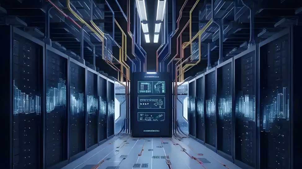
A scalable AI network relies on non-blocking fat-tree topology to deliver predictable east-west bandwidth across thousands of GPUs
The AI Scaling Crisis: Why 88% of Pilots Stall
The statistics are sobering. According to IDC research, for every 33 AI prototypes built, only 4 reach production — an 88% failure rate at the scaling stage. BCG found that just 26% of companies have built capabilities that generate real value beyond pilot projects. And Kore.ai reports that 71% of enterprises identify architecture limitations — not skills, not data, not models — as the single biggest barrier to scaling AI.
The root cause is rarely the algorithm. It is the infrastructure. Traditional data center networks were designed for north-south traffic: user requests flowing in, responses flowing out. AI training fundamentally reverses this pattern. In distributed training across hundreds or thousands of GPUs, the dominant traffic is east-west — massive gradient synchronization exchanges between GPUs that can saturate conventional oversubscribed fabrics in seconds.
What Happens When the Network Fails AI
When GPU clusters are starved of network bandwidth, the consequences cascade quickly:
- Training stalls: GPUs wait for gradient updates, burning compute cycles at $2-$8 per GPU-hour with zero output
- Checkpoint failures: Network timeouts during model checkpointing can corrupt hours of training progress
- Stragglers dominate: In synchronous training, the slowest GPU determines cluster throughput — one congested link can reduce overall efficiency by 30-50%
- Cost explosion: Suboptimal networking can waste billions in processor cycles or require expensive restarts, according to 650 Group
TechRadar reports that 75% of AI projects that fail to scale do so because of data diversity and integration issues — not model deficiencies. The network is the circulatory system of AI infrastructure, and when it cannot move data at the speed and volume that training demands, the entire system collapses.
For a deeper look at how AI workloads reshape cabling requirements, see AMPCOM's guide on AI Infrastructure: How Machine Learning Is Reshaping Data Center Cabling Requirements.
Core Design Principles for Scalable AI Networks
Building a network that scales from a 4-GPU prototype to a 10,000-GPU production cluster requires deliberate architectural decisions from day one. The following principles, drawn from AMD's scalable AI networking framework and real-world hyperscale deployments, form the foundation.
| Principle | What It Means | Why It Matters for AI |
|---|---|---|
| Modularity | Decouple compute, storage, and network layers for independent scaling | Allows GPU count to grow without redesigning storage or management fabric |
| Non-blocking topology | Full bisection bandwidth between all endpoints | Eliminates congestion hotspots during all-to-all gradient synchronization |
| Lossless transport | RDMA with PFC (Priority Flow Control) and ECN marking | Prevents packet loss that forces training restarts |
| DPU offload | Network, security, and storage tasks on dedicated processors | Frees host CPU cycles for AI workloads; enables line-rate telemetry |
| Open standards | Ethernet, UEC, and SONiC over proprietary interconnects | Avoids vendor lock-in; enables multi-supplier sourcing |
| Observability | Real-time telemetry, flow-level visibility, proactive alerting | Detects congestion and link degradation before they stall training jobs |
| Infrastructure abstraction | Orchestration separates workloads from physical resources | Enables hybrid cloud, multi-tenant isolation, and workload mobility |
| Automated lifecycle | MLOps pipelines for CI/CD of models and network configs | Reduces deployment time by 3-5x versus manual handoffs |
Network Topology: Fat-Tree, Spine-Leaf, and Beyond
Topology choice is the single most consequential decision in AI network design. It determines latency, bandwidth, scalability limits, cabling complexity, and cost. Three topologies dominate AI deployments today.
Fat-Tree: The Gold Standard for Non-Blocking Bandwidth
Fat-Tree is a multi-rooted tree architecture where bandwidth increases toward the core, ensuring every path between any two endpoints has equal bandwidth. In a pure fat-tree, every leaf switch connects to every spine switch, creating a non-blocking fabric with 100% bisection bandwidth.
- Bisection bandwidth: 100% (non-blocking)
- Diameter: 4-6 hops (leaf → spine → spine → leaf)
- Scalability: 100,000+ endpoints with 3-tier design
- Best for: 100-5,000 GPU clusters requiring guaranteed bandwidth for all-to-all traffic
- Trade-off: O(N²) cable count — the most cabling-intensive option
Spine-Leaf (CLOS): The Pragmatic Choice
Spine-Leaf is a two-tier CLOS architecture that has become the workhorse of modern data centers. Every leaf switch (ToR) connects to every spine switch, but unlike fat-tree, it allows configurable oversubscription (2:1, 4:1) for cost optimization.
- Bisection bandwidth: 50-100% (configurable)
- Diameter: 2 hops (leaf → spine → leaf) — lower latency than fat-tree
- Scalability: 10,000-100,000 endpoints
- Best for: 100-1,000 GPU clusters with mixed training/inference workloads
- Advantage: Easier incremental scaling — add spine switches as needed
NVIDIA's DGX SuperPOD exemplifies spine-leaf at scale: using Quantum-2 switches (64 ports at 400Gbps), a single SuperPOD delivers 25.6 Tbps of non-blocking bandwidth connecting 20 DGX A100 systems. GIGABYTE's GIGAPOD consolidates 256 GPUs across 8+1 racks using non-blocking fat-tree with spine-leaf architecture.
Dragonfly+: For Extreme Scale
At scales exceeding 10,000 GPUs, Dragonfly+ becomes attractive. It organizes nodes into groups with all-to-all intra-group connectivity and sparse inter-group links, dramatically reducing cable count.
| Dimension | Fat-Tree | Spine-Leaf | Dragonfly+ |
|---|---|---|---|
| Bisection BW | 100% | 50-100% | 40-60% |
| Hop count | 4-6 | 2 | 3 |
| Max scale | 100K nodes | 100K nodes | 1M+ nodes |
| Cable count | Very high | High | Medium (50-70% less) |
| Cost | Highest | Medium | Lowest |
| Best for | LLM training (guaranteed BW) | Mixed workloads | 10K+ GPUs with locality |
For guidance on selecting the right fiber connectors for these high-density topologies, see AMPCOM's Fiber Connector Selection Guide for AI-Era Data Centers.
Topology choice directly impacts latency, bandwidth, cabling cost, and maximum cluster scale
Ethernet vs. InfiniBand: The 2025 Inflection Point
For years, InfiniBand dominated AI back-end networking, holding nearly 80% market share in AI cluster switch sales as recently as 2023. That era is over. According to Dell'Oro Group, Ethernet overtook InfiniBand in AI back-end networking in 2025, reaching more than double InfiniBand's market share.
Why Ethernet Won
- Vendor diversity: Amazon, Microsoft, Meta, Oracle, and xAI all adopted Ethernet for AI back-end networks, driven by supply chain risk mitigation
- Cost economics: Open Ethernet standards enable multi-vendor competition; InfiniBand's single-vendor ecosystem creates pricing leverage
- 800G ramp: 800Gbps Ethernet switches surpassed 20 million ports within three years of shipment — 400Gbps took 6-7 years to reach the same milestone
- Ultra Ethernet Consortium (UEC): Industry alliance developing AI-optimized Ethernet specifications for lossless transport and collective communication
- SONiC adoption: Open network OS accelerating vendor diversity and reducing switching costs
In 2025, Ethernet AI back-end switch sales more than tripled, accounting for over two-thirds of AI cluster data center switch revenue. Celestica and NVIDIA led the market with a combined 50% share, followed by Arista, Cisco, and HPE/Juniper.
Scale-Out vs. Scale-Up
Modern AI networks separate into two distinct domains:
- Scale-up: Connects GPUs within a single rack or chassis (NVIDIA NVLink, UALink). Delivers ultra-high bandwidth for intra-rack communication. 2024 saw scale-up networks escape the server enclosure for the first time with NVIDIA's NVL72. Projected to exceed $10 billion by 2028.
- Scale-out: Connects GPUs across racks and data centers via Ethernet or InfiniBand fabrics. Exceeded $8 billion in revenue in 2025, growing over 100% year-over-year.
AMD's approach unifies both domains: the Pensando Vulcano 800 AI NIC delivers up to 2.4 Tbps of scale-out bandwidth per GPU, while the programmable P4 architecture enables scale-up connectivity through open standards like UALink.
For understanding the design differences between AI front-end and back-end networks, see AMPCOM's analysis of AI Front-End vs. Back-End Networks: Key Design Differences.
5. DPUs and SmartNICs: The Third Pillar of AI Compute
As AI network speeds escalate from 400G to 800G and beyond, host CPUs cannot keep up with packet processing, security enforcement, and telemetry collection. Data Processing Units (DPUs) and SmartNICs offload these tasks to dedicated processors, becoming the third pillar of AI infrastructure alongside CPUs and GPUs.
5.1 What DPUs Do in AI Networks
- Network offload: VxLAN tunneling, RDMA acceleration, routing, and NAT at line rate
- Security: Stateful firewall rules, encryption/decryption, microsegmentation
- Storage: NVMe-oF, compression, deduplication offload
- Telemetry: Flow-level visibility, congestion detection, latency monitoring at line rate
- CPU liberation: Microsoft saved 22 CPU cores per server by offloading connection state to AMD Pensando DPUs
5.2 Real-World DPU Performance
| Metric | AMD Pensando Salina DPU | Competing Solution | Improvement |
|---|---|---|---|
| Packets per second | 117 MPPS | 80 MPPS | 1.45x |
| Line rate | 400 Gbps | 400 Gbps | Parity |
| Programmability | P4 (3rd gen) | Limited | Full programmability |
| CPU core savings | 22 cores/server | 0 | Significant TCO reduction |
In production deployments, Microsoft Azure achieved a 100x improvement in connections-per-second using AMD Pensando DPUs for accelerated networking, while Oracle Cloud reported 5x SDN performance gains. For AI workloads specifically, AMD's Vulcano 800 AI NIC delivers up to 13% improvement in AI job completion times and 33% lower switching costs compared to baseline architectures.
Congestion Management and Lossless Fabrics
AI training workloads generate traffic patterns that are fundamentally hostile to traditional network designs. All-to-all gradient synchronization creates incast — many sources sending to one destination simultaneously — which can overwhelm switch buffers and cause packet loss. In AI training, a single dropped packet can stall the entire job.
Building a Lossless Fabric
Three technologies work together to create lossless AI fabrics:
- PFC (Priority Flow Control): Ethernet's lossless mechanism — when a switch buffer approaches capacity, it sends a PAUSE frame to upstream devices, temporarily halting traffic on that priority class
- ECN (Explicit Congestion Notification): Switches mark packets experiencing congestion, allowing endpoints to proactively reduce transmission rates before buffers overflow
- RDMA (Remote Direct Memory Access): Bypasses host CPU for direct memory-to-memory transfers, reducing latency by 50-80% compared to TCP-based transfers
Rail-Optimized Topology
Modern AI deployments use rail-optimized architectures to minimize congestion. Each GPU server has multiple NICs (typically 8), and each NIC connects to a separate rail — an independent switching fabric. This design creates parallel communication domains that distribute traffic across multiple non-overlapping paths, dramatically reducing incast pressure on any single switch.
For example, with 8 NICs per server and 8 rails, each rail handles only 1/8th of the east-west traffic. This is why NVIDIA's DGX SuperPOD and AMD's Helios architecture both employ rail-optimized designs — it is the most effective way to maintain non-blocking performance at scale.
To understand the physical cabling that supports these high-bandwidth fabrics, see AMPCOM's guide on Different Types of Fiber Optic Cables and DAC Cables: Types, Latency, and Use Cases.
From Pilot to Production: Deployment Best Practices
The journey from pilot to production is where most AI initiatives fail. Here is a structured approach that addresses the architectural, operational, and organizational challenges of scaling AI networks.

A phased deployment approach minimizes risk and ensures the network scales predictably with AI workload growth
Phase 1: Architecture Design
Design Checklist
- Map workload characteristics: model size, parallelism strategy, traffic patterns (all-to-all vs. ring)
- Select topology based on GPU count and growth trajectory (spine-leaf for <1,000 GPUs, fat-tree for 1,000-5,000)
- Choose transport: Ethernet with RoCEv2 for open ecosystems, InfiniBand for maximum single-vendor performance
- Plan for 2-3x bandwidth growth — design cable pathways and power for the next speed tier (800G → 1.6T)
- Integrate DPU/SmartNIC from the start — retrofitting is 3-5x more expensive
Phase 2: Pilot Validation
Start with a single pod (typically 8-32 GPUs) and validate:
- Collective communication performance: Run AllReduce, AllGather, and AlltoAll benchmarks to verify fabric efficiency
- Congestion behavior: Monitor PFC pause frame rates and ECN marking under sustained all-to-all traffic
- Failure recovery: Simulate link failures and measure convergence time — target < 1 second for AI workloads
- Power and thermal: Validate that 800G transceivers and DPUs operate within thermal limits under peak load
Phase 3: Scale-Out Deployment
Scaling Without Disruption
- Pod-based expansion: Add capacity in pre-validated pod units rather than individual racks
- Pre-terminated cabling: Use factory-tested MPO trunk assemblies to reduce on-site installation errors and accelerate deployment
- Network-as-code: Automate switch configuration with SONiC and infrastructure-as-code tools for consistent, repeatable deployments
- Vendor diversification: Qualify at least two switch vendors and two transceiver suppliers to mitigate supply chain risk
- Telemetry pipeline: Deploy streaming telemetry (gNMI, sFlow) before scaling — you cannot manage what you cannot see
Phase 4: Production Operations
- Proactive monitoring: Track GPU utilization, network throughput, and collective operation latency in real-time
- Capacity planning: Monitor link utilization trends and trigger capacity additions at 60% sustained utilization
- Firmware management: Schedule switch and DPU firmware updates during maintenance windows; validate in canary pods first
- Cost optimization: Use workload-aware scheduling to pack training jobs efficiently and minimize idle GPU cycles
For comprehensive cabling management strategies in production data centers, see AMPCOM's Patch Panel Cable Management Guide and Cable Procurement Strategy.
Future-Proofing: Cabling and Bandwidth Strategy
AI network infrastructure is a 7-10 year investment, but bandwidth requirements double every 18-24 months. Designing cabling and bandwidth strategies that survive multiple technology refreshes is critical for protecting capital investment.
The 1.6T Transition
2026 will mark the first volume deployments of 1.6 Tbps (1600G) switches. Dell'Oro Group projects the 1.6T ramp will be even faster than 800G, surpassing 5 million ports within one to two years of initial shipment. Key implications:
- Fiber count per switch port increases — plan for higher density MPO-24 and MPO-32 connectors
- Co-packaged optics (CPO) will begin volume ramp in 2026, integrating optics directly into switch ASICs
- Power consumption per port increases — plan rack power budgets for 1.5-2x current 800G deployments
Cabling Strategy for Multi-Generation Scalability
| Layer | Current (2025-2026) | Next-Gen (2027-2028) | Cabling Recommendation |
|---|---|---|---|
| Intra-rack | 400G DAC / AOC | 800G DAC / AOC | Pre-route OS2 singlemode even if unused; supports all future speeds |
| Inter-rack (ToR-Spine) | 800G SR4 / DR4 | 1.6T DR4 / FR4 | OM4/OM5 multimode for ≤100m; OS2 singlemode for >100m |
| Inter-pod | 800G LR4 / FR4 | 1.6T LR4 | OS2 singlemode with MPO-24 trunk; plan 2x fiber count |
| Inter-data center | 400G ZR / ZR+ | 800G ZR | OS2 singlemode, DWDM-ready, single-fiber bi-directional |
Transceiver Lifecycle Planning
Optical transceivers are the highest-wear component in AI networks, with typical lifespans of 3-5 years under heavy load. Plan replacement budgets accordingly, and monitor optical power levels proactively. See AMPCOM's analysis of optical transceiver lifespan and replacement strategy for detailed guidance.
For high-speed interconnect alternatives, AOC vs. DAC cables each have distinct cost, latency, and distance trade-offs that affect AI cluster design. And for staying ahead of hardware cycles, AMPCOM's NVIDIA 2026 Data Center Roadmap analysis explains what faster GPU refreshes mean for your cabling infrastructure.
Key Questions: Building Scalable AI Networks
Q: Why do 88% of AI pilot projects fail to scale to production?
According to IDC research, only 4 out of 33 AI prototypes reach production. The primary barriers are architectural: 71% of enterprises cite architecture limitations — not skills or data — as the top obstacle. Key failure causes include rigid non-modular designs, lack of MLOps automation, inadequate data pipeline standardization, and insufficient network bandwidth for distributed training. Successful scaling requires modular architecture, automated lifecycle management, and infrastructure designed for east-west traffic patterns from day one.
Q: What is the difference between Fat-Tree and Spine-Leaf topology for AI networks?
Fat-Tree provides 100% non-blocking bisection bandwidth with 4-6 hops between endpoints, ideal for clusters with 100-5,000 GPUs requiring guaranteed bandwidth for all-to-all gradient synchronization. Spine-Leaf is a two-tier CLOS architecture with only 2 hops and 50-100% bisection bandwidth (configurable via oversubscription), making it more cost-effective for 100-1,000 GPU clusters. Fat-Tree requires significantly more cabling (O(N²) cables) but delivers deterministic performance, while Spine-Leaf offers easier incremental scaling and lower cost.
Q: Why did Ethernet overtake InfiniBand in AI back-end networks in 2025?
According to Dell'Oro Group, Ethernet surpassed InfiniBand in AI back-end networking in 2025, reaching more than double InfiniBand's market share. Key drivers include: vendor diversity (Amazon, Microsoft, Meta, Oracle, and xAI all adopting Ethernet), lower cost through open standards, 800Gbps port shipments surpassing 20 million within three years, and the Ultra Ethernet Consortium (UEC) developing AI-optimized Ethernet specifications. Ethernet also enables multi-vendor supply chains, reducing dependency risk compared to InfiniBand's single-vendor ecosystem.
Q: How do DPUs and SmartNICs improve AI network scalability?
DPUs (Data Processing Units) and SmartNICs offload networking, security, and storage tasks from host CPUs, freeing compute resources for AI workloads. AMD Pensando DPUs deliver 117 million packets per second (MPPS) versus 80 MPPS for competing solutions. They enable line-rate VxLAN tunneling, RDMA acceleration, congestion management, and telemetry without CPU overhead. In production, Microsoft achieved 100x improvement in connections-per-second with Pensando DPUs, while Oracle reported 5x SDN performance gains — directly translating to faster AI training and inference.
Q: What is the difference between scale-up and scale-out AI networking?
Scale-up networking connects GPUs within a single rack or chassis (e.g., NVIDIA NVLink, UALink), providing ultra-high bandwidth for intra-rack communication. Scale-out networking connects GPUs across multiple racks and data centers using Ethernet or InfiniBand fabrics. In 2025, scale-out networking exceeded $8 billion in revenue, while scale-up is projected to surpass $10 billion by 2028. Modern AI architectures use both: scale-up for tight GPU coupling within pods, and scale-out for distributed training across pods and data centers.
Q: What bandwidth speeds are used in modern AI data center networks?
Current AI networks predominantly use 400Gbps and 800Gbps Ethernet. In 2025, 800Gbps switches accounted for the vast majority of AI back-end Ethernet shipments, surpassing 20 million ports within three years — compared to 6-7 years for 400Gbps to reach the same milestone. 1.6Tbps (1600Gbps) switches are expected to ship in volume in the second half of 2026, with a ramp projected to be even faster than 800G, surpassing 5 million ports within one to two years. Co-packaged optics (CPO) will further increase bandwidth density.
Q: What are the key design principles for building scalable AI networks?
Core principles include: (1) Modularity — decoupling compute, storage, and network layers for independent scaling; (2) Non-blocking fat-tree or spine-leaf topology for predictable east-west traffic; (3) Lossless fabric with RDMA and congestion control (PFC, ECN); (4) DPU/SmartNIC offload to free host CPUs; (5) Open standards (Ethernet, UEC) to avoid vendor lock-in; (6) Telemetry and observability for proactive fault detection; (7) Infrastructure abstraction through orchestration; (8) Automated lifecycle management with MLOps pipelines.
Q: How should enterprises plan cabling infrastructure for scalable AI networks?
AI network cabling requires high-density fiber trunks (MPO-12/MPO-24) for spine-leaf interconnects, OS2 singlemode for inter-rack distances beyond 100m, and OM4/OM5 multimode for shorter intra-rack connections. Plan for 400G/800G transceiver compatibility using QSFP-DD and OSFP form factors. Use pre-terminated trunk cables to reduce installation time, and design cable management systems that support 2-3x current bandwidth density for future 1.6T upgrades. Always verify bend radius compliance and use bend-insensitive fiber in high-density cabinet environments.
About AMPCOM
AMPCOM is a global supplier of high-performance network infrastructure solutions, specializing in fiber optic and copper cabling systems for AI data centers, enterprise networks, and telecom infrastructure. Our product portfolio includes OS2/OM3/OM4/OM5 fiber patch cables, MPO trunk assemblies, DAC and AOC high-speed interconnects, patch panels, and structured cabling components — all engineered to meet the bandwidth, density, and reliability demands of modern AI workloads.
With 17+ years of experience in enterprise network infrastructure, AMPCOM provides free technical consultation, custom solutions, and rapid global delivery for data center projects of any scale.
Related Articles
- AI Infrastructure: How Machine Learning Is Reshaping Data Center Cabling Requirements — Why AI workloads demand higher fiber counts, bandwidth, and lower latency than traditional computing
- AI Front-End vs. Back-End Networks: Key Design Differences — Understanding the distinct requirements of training fabrics versus inference and management networks
- Fiber Connector Selection Guide for AI-Era Data Centers — Choosing the right MPO, LC, and duplex connectors for 400G/800G AI fabric deployments
- NVIDIA 2026 Data Center Roadmap: What Faster Hardware Cycles Mean for Cabling — Planning infrastructure for accelerating GPU refresh cycles

AMPCOM Technical Team
Industry experts with 17+ years in enterprise network infrastructure and structured cabling systems
Building an AI network that scales?
Our technical team provides free consultation and custom cabling solutions for AI data centers, GPU clusters, and high-performance computing infrastructure worldwide.
Get Free Expert Consultation

