
How Long Can an Ethernet Cable Be Without Losing Speed? Cat5e-Cat8 Limits Explained
Published:Executive Summary: Every Ethernet cable category has a published maximum length — but published maximum and useful maximum are two different things. A Cat6 cable that technically "works" at 100 meters at 1 Gbps is not the same cable that holds 10 Gbps. A Cat8 cable rated for 30 meters will pass traffic at 40 meters — and then silently degrade until the link collapses.
This guide walks through the exact speed-vs-distance thresholds for every major copper Ethernet category, the underlying physics that cap cable length, the four field-proven methods to extend copper links past the 100-meter ceiling, and when to stop fighting physics and switch to fiber. By the end, you will know precisely which cable to order — and at what length — for a build that passes certification on the first attempt.
Quick Navigation
- 1 The 100-Meter Rule: What IEEE 802.3 Actually Requires
- 2 Category-by-Category Speed-Distance Matrix
- 3 Signal Attenuation: The Physics That Caps Copper Distance
- 4 Crosstalk, EMI, and Why Shielding Extends Useful Reach
- 5 PoE and Cable Length: The Voltage Drop Problem
- 6 Extending Beyond 100 Meters: Field-Proven Methods
- 7 Fiber Optic: When Copper Cannot Go the Distance
- 8 Alternative Long-Distance Strategies
- 9 Real-World Deployment Scenarios
- 10 How to Calculate Your Actual Cable Budget
- Q Key Questions About Ethernet Cable Length

Every Ethernet category carries distance-dependent speed limits — the right choice depends on both the throughput you need and the span you must cover
1. The 100-Meter Rule: What IEEE 802.3 Actually Requires
The number that appears in every Ethernet cable specification — 100 meters, or 328 feet — is not a suggestion. It is a physical design constraint baked into the IEEE 802.3 Ethernet standard. The 100-meter horizon traces back to the original 10BASE-T specification published in 1990, and every copper Ethernet variant since then — 100BASE-TX, 1000BASE-T, 10GBASE-T, and 25G/40GBASE-T — inherits the same ceiling.
But the 100-meter figure is not a single cable. The IEEE 802.3 channel model defines it as 90 meters of solid-core horizontal cable plus 10 meters of stranded patch cord — 5 meters at each end, connecting the wall outlet to the end device on one side and the patch panel to the switch on the other. When a certification tester runs a Permanent Link test, it measures only the 90-meter installed run. When it runs a Channel test, it includes the patch cords.
The 100-meter limit is not arbitrary. It is the longest distance an electrical signal can travel over twisted-pair copper and still arrive at the receiver with enough amplitude, sufficiently low distortion, and sufficiently low noise floor for the DSP (Digital Signal Processor) inside the PHY chip to recover the original bitstream. Push past 100 meters and the signal-to-noise ratio collapses — the DSP cannot tell a one from a zero with enough statistical confidence, and the link either negotiates down to a slower speed or drops entirely.
2. Category-by-Category Speed-Distance Matrix
The 100-meter ceiling applies to all copper Ethernet categories — but the speed you can sustain within that span depends entirely on the cable's bandwidth rating, twist-rate precision, and shielding construction. The table below is your reference for every purchasing decision.
| Category | Bandwidth | Max Speed | Max Distance at Max Speed | Speed at 100 m | IEEE Standard | Typical Application |
|---|---|---|---|---|---|---|
| Cat5e | 125 MHz | 1 Gbps | 100 m | 1 Gbps | 1000BASE-T | Small office, residential, basic PoE endpoints |
| Cat6 | 250 MHz | 10 Gbps | 55 m | 1 Gbps | 10GBASE-T | SMB networks, short-haul 10G within a rack row |
| Cat6a | 500 MHz | 10 Gbps | 100 m | 10 Gbps | 10GBASE-T | Enterprise horizontal cabling, PoE++ backhaul |
| Cat7 | 600 MHz | 10 Gbps / 40 Gbps | 100 m / 50 m | 10 Gbps | ISO/IEC 11801 Class F | High-EMI industrial, broadcast, lab instrumentation |
| Cat8 | 2000 MHz | 25 / 40 Gbps | 30 m | N/A | 25G/40GBASE-T | Data center ToR switch-to-server edge links |
The most misunderstood entry in this table is Cat6 at 10 Gbps. Many spec sheets print "Cat6 — 10 Gbps — 100 meters" without the qualification. The truth: Cat6 only holds 10GBASE-T to 55 meters. Between 55 and 100 meters, the link auto-negotiates to 1 Gbps — and if your switch is configured to force 10 Gbps, the link may not come up at all. This single fact has derailed more network upgrade projects than any other cabling mistake.
Cat8 deserves a special warning. It is the only copper Ethernet category that cannot reach 100 meters at any speed. Its 2 GHz operating frequency — 20 times that of Cat5e — means the signal attenuates so rapidly that the receiver can only recover it within 30 meters. Cat8 was designed for data center edge applications: connecting a Top-of-Rack switch to servers in the same and adjacent cabinets. It is not a horizontal cabling product. Do not pull Cat8 through walls, ceilings, or floor conduits.

Signal amplitude drops predictably with distance — higher-bandwidth categories attenuate faster, explaining why Cat8 loses useful reach at just 30 meters
3. Signal Attenuation: The Physics That Caps Copper Distance
Attenuation is the gradual loss of signal strength as an electrical waveform travels down a copper conductor. It is measured in decibels (dB) per 100 meters and increases with both cable length and signal frequency. At 100 MHz (Cat5e's ceiling), a quality Cat5e cable might measure 22 dB of attenuation over 100 meters — the signal arriving at the receiver is roughly 1/160th the amplitude of the transmitted signal. At 500 MHz (Cat6a's ceiling), attenuation climbs past 40 dB — the receiver sees about 1/10,000th of the original signal. The PHY chip's DSP must reconstruct the bitstream from this whisper.
3.1 Insertion Loss: The Certifier's Verdict
In structured cabling certification, attenuation is quantified as insertion loss — the total power lost between the transmitter and the receiver, expressed in dB. The TIA-568.2-D standard defines maximum insertion loss values at each frequency for every category. A Cat6a channel at 500 MHz must measure no more than 39.1 dB of insertion loss. If your certifier reports 39.5 dB, the link fails — even if data passes through it during a simple ping test. Marginal insertion loss links often work on day one and fail a year later as connectors oxidize and temperature shifts.
3.2 Return Loss: The Echo That Steals Bandwidth
Return loss measures how much signal energy reflects back toward the transmitter due to impedance mismatches along the cable. Every connector, every kink, and every manufacturing inconsistency in the twisted pair creates a tiny impedance discontinuity. The reflected energy behaves like an echo — it arrives back at the transmitter and interferes with the outgoing signal. At gigabit speeds and above, where all four pairs transmit and receive simultaneously (full-duplex), return loss directly reduces usable bandwidth. Poor termination technique — untwisting pairs too far from the connector, inconsistent crimping — is the number one cause of return loss failures in the field.
Attenuation Checklist: What Installers Must Verify
- Solid copper only for horizontal runs. Copper-Clad Aluminum (CCA) cable has approximately 40% higher DC resistance than solid copper — it will fail insertion loss testing at distances far shorter than 100 meters.
- Do not exceed the 90-meter Permanent Link limit. Leave 10 meters total for patch cords. If your longest horizontal run measures 93 meters, someone needs to re-route.
- Verify minimum bend radius. Cat6a and above require a minimum bend radius of 4x the cable outer diameter during installation. A kinked cable at a ceiling corner can add 2-3 dB of insertion loss at high frequencies.
- Cable management: no zip ties cinched tight. Over-compressed cable bundles distort the twist geometry and increase alien crosstalk. Use Velcro wraps with light tension.
4. Crosstalk, EMI, and Why Shielding Extends Useful Reach
Attenuation is only half the story. The other half is noise — and the longer the cable, the more noise it picks up. Two noise mechanisms determine whether a signal can be recovered at a given distance.
4.1 Near-End Crosstalk (NEXT) and Alien Crosstalk (ANEXT)
NEXT measures the interference that one pair induces into an adjacent pair within the same cable, measured at the near end. It is the primary crosstalk metric for frequencies up to 250 MHz (Cat6). ANEXT — alien crosstalk — measures interference between adjacent cables in a bundle. ANEXT becomes the dominant noise source in Cat6a and above because the tighter twist rates and higher frequencies cause signals to radiate more energy into neighboring cables. A bundle of 48 Cat6a cables in a cable tray, all carrying 10GBASE-T traffic, generates measurable ANEXT that can push marginal links over the certification threshold.
4.2 Shielded vs. Unshielded: The Distance Advantage
Unshielded twisted pair (U/UTP) relies entirely on precise pair geometry — twist rates, pair separation, and the common-mode rejection of differential signaling — to suppress crosstalk. It works remarkably well in electrically quiet environments. But as frequency and cable density increase, UTP's noise margin shrinks.
Shielded cable — particularly S/FTP construction with individual foil-wrapped pairs and an overall tinned-copper braid — adds two layers of defense. The individual pair foils block pair-to-pair crosstalk (improving NEXT and PSNEXT margins by 10-15 dB), and the overall braid blocks alien crosstalk and external EMI. In practical terms, a well-grounded S/FTP Cat6a link at 100 meters often shows 3-5 dB better insertion loss margin than an equivalent U/UTP Cat6a link — not because shielding reduces attenuation, but because it eliminates the noise floor that the PHY's DSP must overcome.
More details ablout the the deference about Shielded and Unshielded, see our blog: Shielded vs Unshielded Ethernet Cable - Which Should You Choose?
5. PoE and Cable Length: The Voltage Drop Problem
Power over Ethernet adds a second physical constraint to cable length: DC resistance. Data signals only care about high-frequency impedance and insertion loss. DC power cares about the simple resistance of the copper conductor — and that resistance scales linearly with length.
5.1 The Numbers: Voltage Drop at Each PoE Level
A 100-meter run of 23 AWG solid copper Cat6a has a DC loop resistance of approximately 12.5 ohms. At PoE Type 1 (IEEE 802.3af, 15.4W), the current draw is roughly 350 mA. Voltage drop across the cable: 4.4V. The powered device receives approximately 43.6V — well within the 37-57V operating range. At PoE Type 4 (IEEE 802.3bt, 90W at the PSE), the current draw can reach 960 mA per pair. Voltage drop across the same 100-meter run: 12V. The device receives roughly 42V — still within spec, but with little margin remaining if the PSE output is on the low end of its tolerance range.
For a deep dive into PoE standards— 802.3af, 802.3at & 802.3bt, see our PoE Standards: 802.3af, 802.3at & 802.3bt Complete Glossary.
| PoE Standard | PSE Output | Max Current per Pair | Voltage Drop (100 m, 23 AWG) | Voltage at PD | Distance Limit |
|---|---|---|---|---|---|
| 802.3af (Type 1) | 15.4W | 350 mA | ~4.4V | ~43.6V | 100 m |
| 802.3at (Type 2) | 30W | 600 mA | ~7.5V | ~42.5V | 100 m |
| 802.3bt (Type 3) | 60W | 600 mA (4-pair) | ~7.5V | ~42.5V | 100 m |
| 802.3bt (Type 4) | 90W | 960 mA (4-pair) | ~12.0V | ~42.0V | 100 m* |
*Type 4 at 100 meters requires 23 AWG or thicker solid copper conductors. 24 AWG or CCA cable will not reliably deliver 90W at full distance.
5.2 The Heat Problem No One Talks About
DC resistance in copper converts electrical power to heat. In a bundle of 48 Cat6a cables, each carrying 60W of PoE, the total dissipated power is approximately 15-20W per meter of bundle — equivalent to a small space heater running inside your cable tray. This heat increases conductor resistance (copper's temperature coefficient is approximately 0.393% per degree Celsius), which increases voltage drop, which generates more heat. Thermal runaway is possible in poorly ventilated pathways.
The 2023 revision of the National Electrical Code (NEC) introduced ampacity derating tables for bundled PoE cables. If you are running more than 24 PoE cables in a single bundle, consult your local electrical code. You may need to reduce bundle sizes, specify higher-temperature-rated cable jackets, or separate data and power pathways.

PoE simplifies endpoint deployment — but cable length and conductor gauge directly determine whether powered devices receive enough voltage to operate
6. Extending Beyond 100 Meters: Field-Proven Methods
The 100-meter limit is a hard ceiling — but it is a per-segment ceiling, not a per-link ceiling. Four field-proven methods extend Ethernet connectivity beyond 100 meters, each with distinct trade-offs in cost, latency, and deployment complexity.
6.1 Network Switch as a Signal Repeater (Up to ~300 m)
The simplest extension method: place a network switch at the 100-meter mark. The switch receives the signal, decodes it, regenerates it with a clean clock, and forwards it out another port. The next segment gets a fresh 100-meter budget. Daisy-chaining three switches yields roughly 300 meters of usable reach. This approach requires power at each switch location and introduces approximately 5-10 microseconds of latency per hop — negligible for most applications but measurable in high-frequency trading or industrial real-time control systems.
6.2 Ethernet Extender (Up to ~1,900 m over Copper)
Ethernet extenders use VDSL2 (Very-high-bit-rate Digital Subscriber Line) technology to push Ethernet over a single pair of copper wire — often existing telephone wiring — at distances up to 1,900 meters. They operate at lower frequencies than standard Ethernet (sub-30 MHz) to minimize attenuation. The trade-off: bandwidth drops with distance. A typical VDSL2 extender delivers 100 Mbps at 300 meters, 50 Mbps at 1,000 meters, and roughly 10 Mbps at 1,900 meters. Extenders work in pairs — transmitter at the switch end, receiver at the device end — and are commonly used for connecting remote IP cameras, access control panels, and sensors in parking lots, warehouses, and campus perimeters.
6.3 PoE-Powered Repeater (Up to ~500 m)
PoE repeaters are inline devices that regenerate both data and power without requiring a local AC outlet. They draw their operating power from the PoE source and pass through a refreshed PoE budget to the next segment. Each repeater adds a fresh 100-meter copper segment. The limiting factor is the PoE power budget: each repeater consumes 3-5W for its own operation, reducing the power available downstream. With Type 4 (90W) at the source, you can typically cascade two repeaters for ~300 meters while still delivering 30W to an endpoint; three repeaters may be possible if the endpoint is a low-power device like a sensor or camera.
6.4 Fiber Media Converter (Unlimited for Practical Purposes)
A fiber media converter is an inline device with an RJ45 port on one side and an SFP slot on the other. It converts the electrical Ethernet signal to an optical signal, which travels through fiber to a matching converter at the far end, where it is converted back to copper Ethernet. This is the solution when you need 1 Gbps or 10 Gbps at any distance beyond 300 meters. Fiber optic cable attenuates at roughly 0.35 dB/km — compared to 22 dB/100m for Cat5e copper — meaning a single-mode fiber link can carry 10 Gbps over 40 kilometers without any intermediate active equipment. See Section 7 for a detailed fiber comparison.
7. Fiber Optic: When Copper Cannot Go the Distance
There is a point in every network design where copper stops making sense and fiber becomes the only defensible choice. That threshold is typically between 200 and 300 meters — well within the technical limits of Ethernet extenders, but past the point where copper's cost, fragility, and bandwidth degradation justify switching media.
| Fiber Type | Core Diameter | 10 Gbps Reach | 100 Gbps Reach | Attenuation | Use Case |
|---|---|---|---|---|---|
| OM3 (Multimode) | 50 µm | 300 m | 100 m | 3.0 dB/km @ 850 nm | Intra-building backbone, data center rows |
| OM4 (Multimode) | 50 µm | 550 m | 150 m | 3.0 dB/km @ 850 nm | Data center spine-leaf, campus backbone < 550 m |
| OS2 (Singlemode) | 9 µm | 40 km | 40 km | 0.35 dB/km @ 1310 nm | Inter-building, campus, metro, WAN |
The economics favor fiber sooner than most network planners expect. A pair of Gigabit Ethernet media converters costs roughly $60-100. A 200-meter outdoor-rated OS2 fiber patch cable with LC connectors costs roughly $40-80. For $100-180 total, you get a link that will carry 10 Gbps tomorrow by swapping the SFP modules — no new cable pull required. Compare that to trenching and pulling new copper every time bandwidth requirements double.
Case Study: Warehouse to Admin Building — Copper vs. Fiber Decision
A logistics company needed to connect IP cameras and an access control server in a warehouse to the main network in an admin building 180 meters away. The initial plan: two Cat6a outdoor-rated cables in underground conduit with PoE extenders at the 90-meter mark.
The problem: The conduit passed within 3 meters of a 480V three-phase motor feed for the warehouse conveyor system. The resulting EMI would have saturated the unshielded Cat6a, producing intermittent camera dropouts and corrupted access control logs.
The solution: A single OS2 single-mode fiber pair in the same conduit — immune to EMI by design — with a pair of Gigabit media converters at each end. Total material cost was $40 higher than the copper plan. No PoE extenders, no mid-span power, no ongoing troubleshooting.
Result: Zero link errors in 18 months of operation. When the company expanded the camera network to 4K resolution, the same fiber pair handled the increased bandwidth by swapping SFP modules from 1G to 10G — with no new cable pull.
8. Alternative Long-Distance Strategies
When pulling new cable — copper or fiber — is impractical due to building construction, lease restrictions, or cost, four alternative technologies can bridge Ethernet across long distances using existing infrastructure.
8.1 MoCA (Multimedia over Coax Alliance) — Up to 300 m
MoCA 2.5 adapters use existing coaxial cable — the same RG-6 cabling that carries cable TV — to deliver up to 2.5 Gbps of Ethernet throughput. Maximum node-to-node distance is approximately 300 meters over RG-6. Latency is around 3.5 milliseconds — higher than direct Ethernet but acceptable for streaming, surveillance, and general data. MoCA is most commonly deployed in residential and hospitality environments where existing coaxial infrastructure is already in place.
8.2 Powerline Networking — Up to 300 m (Unreliable Beyond 150 m)
Powerline adapters (HomePlug AV2) modulate Ethernet data onto existing AC power wiring. Maximum rated distance is 300 meters, but real-world throughput drops sharply beyond 150 meters and whenever the signal crosses circuit breakers, phases, or surge protectors. Expect 100-200 Mbps under ideal conditions, and substantially less in buildings with older wiring, multiple sub-panels, or heavy motor loads on the same circuits. Powerline is a last-resort solution — it works, but it is not reliable enough for anything beyond residential convenience networking.
8.3 Wireless Point-to-Point Bridge — Up to Several Kilometers
For building-to-building links where trenching is impossible — across roads, rivers, or leased properties — a 60 GHz wireless bridge (802.11ad/ay) provides gigabit throughput over distances up to 2-3 kilometers with clear line of sight. 5 GHz bridges extend to 10+ kilometers at lower throughput. Wireless bridges introduce 1-3 milliseconds of latency and are susceptible to rain fade at 60 GHz. They are the pragmatic choice when fiber is not an option, but they are not a replacement for fiber in mission-critical backbone links.
9. Real-World Deployment Scenarios
The right cable category and distance strategy depends on the deployment context. Here is what works — and what does not — in the most common scenarios.
9.1 Small-to-Medium Business Office (Sub-80 m Runs)
Recommended: Cat6a U/UTP
In a standard office layout — cubicles, conference rooms, a small server closet — most horizontal runs fall well under 80 meters. Cat6a U/UTP delivers 10 Gbps across the full distance budget, supports PoE++ for desktop phones and Wi-Fi 6E access points, and costs only marginally more than Cat6. The extra bandwidth headroom (500 MHz vs. 250 MHz) means the same cable plant will handle the next generation of endpoint devices without replacement.
Why not Cat6: The 55-meter 10G limit means any run to a corner office or conference room that exceeds 55 meters will not support 10GBASE-T. Cat6 saves roughly 15% on cable cost but locks the building into 1 Gbps for any run between 55 and 100 meters — a false economy.
9.2 Data Center ToR/Spine-Leaf (Sub-30 m Runs)
Recommended: Cat8 S/FTP for Copper, OM4/OS2 for Fiber Uplinks
Within a data center rack row, switch-to-server links rarely exceed 15 meters. Cat8 S/FTP delivers 25 Gbps or 40 Gbps at these distances — matching or exceeding SFP28 direct-attach copper (DAC) performance with the flexibility of field-terminated connectors. For spine-to-leaf uplinks exceeding 30 meters, OM4 multimode fiber with 100GBASE-SR4 transceivers handles distances up to 100 meters; beyond that, OS2 single-mode with 100GBASE-LR4 reaches 10 kilometers.
Why not Cat6a for ToR: Cat6a is physically bulkier than Cat8 and does not support 25GBASE-T or 40GBASE-T. In a high-density 48-port ToR switch, the larger cable diameter and bend radius of Cat6a obstructs airflow and complicates cable management. Cat8's smaller diameter and higher speed rating make it the superior choice for short-reach data center copper.
9.3 Campus Backbone (100 m – 2 km Between Buildings)
Recommended: OS2 Singlemode Fiber
For any link connecting separate buildings on a campus, copper is not an option. Even if the distance is only 120 meters — technically extendable with a switch — the risk of ground potential differences between buildings, lightning-induced surges on outdoor copper, and the inevitable bandwidth upgrade demand within 3-5 years make fiber the only reasonable choice. OS2 single-mode fiber in an underground conduit, terminated to LC/UPC connectors at both ends, delivers 10 Gbps to 100 Gbps with zero active electronics between buildings.
9.4 Industrial / Manufacturing Floor (High EMI, Sub-100 m)
Recommended: Cat7 or Cat6a S/FTP, Shielded Connectors, Continuous Bonding
Manufacturing floors with VFD motor drives, welders, and high-current switchgear generate broadband EMI that saturates unshielded cable. S/FTP construction — individual foil-wrapped pairs plus an overall braided shield — is mandatory. The shield must be bonded to ground at both ends through shielded RJ45 connectors, shielded patch panels, and a properly bonded equipment rack. Do not mix shielded cable with unshielded connectors — a single break in the shielding chain compromises the entire link's noise immunity.
10. How to Calculate Your Actual Cable Budget
Every network cabling project starts with a site walk and a cable schedule. Getting the distance calculation right on paper prevents expensive surprises during certification. Here is the formula that professional installers use.
10.1 The Permanent Link + Patch Cord Equation
Cable Budget Formula
Channel Length = Permanent Link + Patch Cord A + Patch Cord B
Where:
- Permanent Link = the installed horizontal cable from patch panel to wall outlet (90 m max)
- Patch Cord A = the cable from switch to patch panel (typically 3-5 m)
- Patch Cord B = the cable from wall outlet to end device (typically 3-5 m)
- Channel = the end-to-end signal path (100 m max per IEEE 802.3)
Example: Your site survey measures 82 meters from the telecom room patch panel location to the farthest office wall outlet. Add 5 meters for the switch-to-patch-panel cord and 3 meters for the PC-to-wall-outlet cord. Total channel: 90 meters — safely within the 100-meter limit with 10 meters of margin.
Example that fails: The same building has a warehouse extension where the measured cable path is 94 meters. Add 5 meters and 3 meters for patch cords. Total channel: 102 meters — exceeding the IEEE 802.3 limit. You have two choices: relocate the telecom room closer to the warehouse, or switch to fiber for that specific run.
Pre-Purchase Distance Verification Checklist
- Measure the actual cable pathway — not the straight-line distance. Cable must route around corners, through conduit bends, and along cable trays. Add 10-15% to every straight-line measurement for pathway routing.
- Add service loops. Leave 2-3 meters of slack at each end for re-termination. A connector that fails certification can be cut off and re-terminated if there is slack — if not, the entire cable pull is wasted.
- Account for vertical rise. Cables running between floors add 3-5 meters of vertical distance per floor, plus horizontal travel from riser to outlet.
- Verify cable category at your measured distance. If your longest run is 65 meters, Cat6 handles 10 Gbps. If your longest run is 75 meters, Cat6 will not — you need Cat6a.
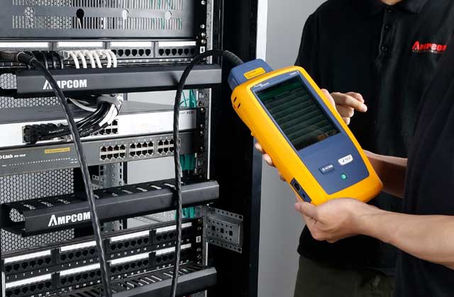
Certification testing validates that every run meets its category's insertion loss, NEXT, and return loss specifications — a cable that "works" is not the same as a cable that passes
Key Questions About Ethernet Cable Length Limits
Q1: What is the maximum length of an Ethernet cable without losing speed?
It depends on the cable category and the target speed. For Cat5e at 1 Gbps: 100 meters. For Cat6a at 10 Gbps: 100 meters. For Cat6 at 10 Gbps: 55 meters — beyond that, speed drops to 1 Gbps. For Cat8 at 25-40 Gbps: 30 meters. The 100-meter figure is the maximum channel length (permanent link plus patch cords), not the maximum cable length.
Q2: Does Ethernet cable length affect speed?
Not within the rated distance. A 10-meter Cat6a cable and a 100-meter Cat6a cable both deliver 10 Gbps — there is no gradual speed reduction inside the rated range. The performance is binary: within spec, you get full speed; beyond spec, the link either auto-negotiates to a lower speed or fails. However, cables approaching the maximum distance have lower signal-to-noise margin and are more susceptible to environmental noise and temperature-driven degradation over time.
Q3: Can I run Ethernet cable longer than 100 meters?
Not directly with a single unbroken copper segment. The IEEE 802.3 standard does not define any copper Ethernet PHY operation beyond 100 meters. You can extend connectivity beyond 100 meters using a network switch as a repeater (yielding another 100-meter segment), an Ethernet extender using VDSL2 over existing copper pairs (up to 1,900 meters at reduced speed), a PoE-powered repeater, or a fiber media converter (up to 40+ kilometers with single-mode fiber).
Q4: How far can Cat6 carry 10 Gbps?
Cat6 supports 10GBASE-T up to 55 meters (180 feet). Between 55 and 100 meters, the link auto-negotiates to 1 Gbps. If your deployment requires 10 Gbps at distances beyond 55 meters, you must use Cat6a or Cat7 — both support 10 Gbps over the full 100-meter channel. The limiting factor is Cat6's 250 MHz bandwidth; 10GBASE-T signaling requires the cable to pass frequencies up to 400 MHz, which Cat6 can only sustain over shorter distances.
Q5: How long can a Cat8 Ethernet cable be?
Cat8 is rated for 30 meters (98 feet) when running at 25 Gbps or 40 Gbps. It operates at 2 GHz — 20 times the frequency of Cat5e — which causes rapid signal attenuation. Cat8 was designed exclusively for data center edge applications (switch-to-server within the same rack row) and is not intended for horizontal cabling, building backbone, or campus links. Do not purchase Cat8 for office or residential installations; it provides no speed benefit over Cat6a at those distances and costs significantly more.
Q6: Does PoE reduce the maximum Ethernet cable length?
The data distance limit remains 100 meters regardless of PoE. However, at higher PoE levels — particularly IEEE 802.3bt Type 4 (90W) — DC voltage drop across the copper becomes significant. A 100-meter run of 23 AWG cable carrying 90W loses approximately 12V to conductor resistance. This leaves the powered device operating near the lower end of its acceptable voltage range. Always use 23 AWG solid copper for Type 3 and Type 4 PoE deployments at maximum distance. 24 AWG or thinner conductors will cause the device to brown out under load.
Q7: Is fiber optic better than Ethernet for long distances?
Yes — unequivocally. Singlemode fiber (OS2) carries 100 Gbps over 40 kilometers with no active regeneration. It has several orders of magnitude lower attenuation than copper (0.35 dB/km vs. ~200 dB/km), is immune to electromagnetic interference, and eliminates the ground potential difference problems that plague outdoor copper links. The only reason to use copper for distances beyond 100 meters is if existing copper infrastructure (phone lines, structured cabling) is already installed and re-trenching is cost-prohibitive.
Q8: What symptoms indicate an Ethernet cable is too long?
Watch for these indicators: (1) The link auto-negotiates to a speed lower than both the switch port and the device support — for example, a 10G switch and 10G NIC negotiating at 1 Gbps. (2) Intermittent link drops that correlate with temperature changes — as copper warms, its resistance increases, pushing marginal insertion loss over the edge. (3) Elevated CRC and FCS error counters on the switch port. (4) Poor VoIP call quality or video stream buffering on what should be a sufficient bandwidth link. If a Fluke or equivalent certifier reports insertion loss within 1 dB of the category limit, the cable is running on borrowed time.
About AMPCOM Ethernet Cables
AMPCOM manufactures a complete range of copper Ethernet cables engineered to meet or exceed TIA-568.2-D and ISO/IEC 11801 performance specifications — category by category, meter by meter:
- Cat6a S/FTP Tough Armor: Double-shielded (individual foil-wrapped pairs + tinned-copper braid) for 10GBASE-T at the full 100-meter channel. Abrasion-resistant jacket designed for data center MAC-heavy environments.
- Cat6a U/UTP Velocity LSZH: Unshielded, low-smoke zero-halogen jacket for commercial office horizontal cabling where fire code mandates LSZH. Full 500 MHz bandwidth, 10 Gbps to 100 meters.
- Cat8 S/FTP: 2 GHz bandwidth, 25G/40GBASE-T up to 30 meters. Individually foil-wrapped pairs, overall braid, gold-plated shielded RJ45 connectors. Built for ToR and edge data center patching.
- Cat7 S/FTP: 600 MHz, 10 Gbps to 100 meters. Individual pair shielding plus overall braid for industrial environments with high EMI — VFD drives, welding equipment, power distribution rooms.
- Cat5e U/UTP: 100 MHz, 1 Gbps to 100 meters. Cost-effective for basic office connectivity, IP phone backhaul, and low-bandwidth PoE endpoints.
All AMPCOM copper cables use solid bare copper conductors — never copper-clad aluminum (CCA). Every reel includes test reports showing compliance with insertion loss, NEXT, PSNEXT, ACR-F, and return loss limits per the relevant category standard. For projects requiring third-party certification, ISO 17025-accredited lab reports are available on request.
Related Articles
- STP vs UTP Cable: Complete Terminology Guide — Decode every ISO/IEC 11801 shielding code: U/UTP, F/UTP, S/FTP, SF/FTP, and when each construction type is required.
- Shielded vs Unshielded Cable: How to Choose — Decision framework for matching cable shielding to EMI environment, grounding infrastructure, and budget.
- Structured Cabling for AI Data Centers: What Is Changing — How GPU cluster bandwidth demands are rewriting cable specifications for density, distance, and power delivery.
- MPO Fiber Solutions: Choosing 8, 12, or 24 Fibers for High-Density Cabling — Selecting the right MPO configuration for 40G, 100G, and 400G parallel optics — the other side of the distance equation.

AMPCOM Technical Team
Industry experts with 17+ years in enterprise network infrastructure, structured cabling design, and field certification testing
Not sure which cable category and length your project needs?
Send us your floor plan and port schedule. Our engineering team will return a complete cable specification — category, shielding type, jacket rating, and verified maximum distance — at no cost.
Get Your Free Cable Specification

