
How to Install STP Cables with Proper Grounding: A Complete Guide for EMI-Free Networks
Published:Executive Summary: The global shielded twisted pair (STP) cable market reached $6.61 billion in 2025, growing at 6.5% CAGR through 2032 — yet up to 70% of STP installation failures trace back to one root cause: improper grounding. A shield left floating or bonded incorrectly becomes an antenna that collects EMI and redistributes it along your entire cable run, making performance worse than cheap unshielded cable. This guide walks through every step — from shield type selection and EMI assessment to single-end bonding, termination, and Fluke certification — so your shielded Ethernet investment actually delivers the noise immunity you paid for.
Quick Navigation
- 1 Why STP Grounding Makes or Breaks Your Network
- 2 Shield Types Decoded: F/UTP, U/FTP, S/FTP, and SF/UTP
- 3 EMI Environment Assessment: When STP Is Justified
- 4 Grounding Architecture: TIA-607, Single-End Bonding, and Building Ground
- 5 Step-by-Step Installation: From Cable Prep to Shield Termination
- 6 Common Installation Failures and Their Hidden Costs
- 7 Testing and Certification: Proving the Shield Works
- 8 Deployment Scenarios: Data Centers, Industrial, and Outdoor
- 9 Key Questions (FAQ)

Proper single-end grounding at the patch panel transforms the shield from a liability into effective EMI protection
1. Why STP Grounding Makes or Breaks Your Network
The numbers tell a clear story. The global STP cable market stood at $6.61 billion in 2025, with data centers consuming 38.8% of all shielded cable produced. Cat6 and Cat6A account for 47.5% of that volume, and the Asia-Pacific region alone represents $2.71 billion in annual demand. Yet market growth masks a persistent engineering problem: many of these installations will never deliver the EMI protection the cable was designed to provide.
Here is the fundamental principle that too many installers learn the hard way: a shield without proper grounding is worse than no shield at all. When the shield floats — disconnected from a stable ground reference — it acts as a large antenna, capturing electromagnetic interference from motors, fluorescent ballasts, HVAC equipment, and adjacent power lines, then redistributing that noise along the entire length of the cable run. The result is a network that performs worse than a properly installed UTP system in the same environment.
The physics is straightforward. A properly grounded shield functions as a Faraday cage, intercepting external electromagnetic fields and safely diverting the induced current to ground before it reaches the signal conductors. An ungrounded or poorly grounded shield cannot discharge that energy, so it capacitively couples noise directly into the twisted pairs it was supposed to protect. Whether you are running STP cable in an industrial control cabinet or pulling shielded Cat6A through a hyperscale data center, the grounding scheme determines whether your investment pays off or backfires.
2. Shield Types Decoded: F/UTP, U/FTP, S/FTP, and SF/UTP
Not all shielded cables are created equal. The naming convention — defined under ISO/IEC 11801 — uses a two-part code: the first letter describes the overall shield around all four pairs, and the second describes the individual pair shielding. Understanding these differences is the first step in selecting the right cable for your EMI environment.
| Shield Type | Construction | EMI Protection | Best Application | Grounding Complexity |
|---|---|---|---|---|
| F/UTP | Overall aluminum foil around all 4 pairs | Moderate — blocks high-frequency EMI | Commercial buildings, Cat6A data centers with moderate noise | Low — single drain wire |
| U/FTP | Individual foil on each pair, no overall shield | Good pair-to-pair crosstalk control | High-performance links, dense bundle installations | Moderate — 4 separate foils to manage |
| S/FTP | Overall braid + individual pair foils | Maximum — braid for low-freq, foils for high-freq | Industrial, high-EMI, Cat7/Cat8 environments | Higher — braid and foils require careful termination |
| SF/UTP | Overall braid + overall foil, no pair shields | Strong overall EMI barrier | Factory automation, outdoor security networks | Moderate — two overall shields to bond |
The drain wire — a bare tinned copper conductor running alongside the foil shield — is the critical component that makes grounding possible. It provides a low-impedance path from the shield to the grounding point. When terminating, the drain wire must be securely connected to the shielded connector's ground tab or the patch panel's bonding strip. Cutting it short, leaving it loose, or forgetting it entirely are among the most common termination errors.
For practical selection, AMPCOM's Tough Armor S/FTP patch cables and Velocity LSZH S/FTP cables combine braid-and-foil shielding with LSZH jackets, making them suitable for both data center and industrial deployments where EMI and fire safety requirements intersect. For a deeper comparison of shielded versus unshielded options, see this shielded vs. unshielded patch cable guide.

Shield construction determines both EMI effectiveness and grounding complexity — choose based on your actual noise environment
3. EMI Environment Assessment: When STP Is Justified
Selecting shielded cable should be driven by actual interference risk, not the assumption that more shielding is always better. A structured assessment of the installation environment saves money and prevents the most expensive mistake: installing STP where UTP would perform identically, then grounding it incorrectly and ending up with worse performance than the UTP alternative.
Identifying EMI Sources
Walk the planned cable routes and identify what the cables will pass near. Common noise sources include:
- Motors and variable frequency drives (VFDs) — the dominant EMI source in industrial environments
- Fluorescent light ballasts — often overlooked in office retrofits
- HVAC equipment and transformers — generate low-frequency magnetic fields
- Elevator shafts and generator rooms — high-energy interference zones
- UPS systems and power distribution units — especially in data center aisles
- High-voltage power lines — inductive coupling over parallel runs
Any cable run passing within 300mm (12 inches) of these sources should be evaluated for shielded cable. When crossings are unavoidable, route communication cables perpendicular to power lines rather than parallel to minimize inductive coupling. For more on UTP's limitations in noisy settings, see this analysis of UTP EMI resistance.
The Ground Quality Check
Before specifying STP, confirm that your building has a clean, properly bonded ground system. A floating or poor-quality ground makes shielded cable unreliable. If ground quality cannot be verified or improved, a correctly installed UTP system will outperform an improperly grounded STP system every time. This is not a minor caveat — it is the single most common reason STP installations fail certification.
Also consider the alien crosstalk (ANEXT) environment. In high-density data center cable bundles, STP's shield provides additional ANEXT margin that UTP cannot match, making it the preferred choice for Cat6A installations where bundles exceed 24 cables in shared pathways.
4. Grounding Architecture: TIA-607, Single-End Bonding, and Building Ground
Grounding is not an afterthought — it is a system that must be designed before the first cable is pulled. The TIA-607 standard defines the telecommunications grounding and bonding framework that bonds equipment racks and patch panels to the building's main grounding system through a structured hierarchy of busbars and bonding conductors.
The TIA-607 Grounding Hierarchy
In a properly designed installation, the grounding chain works as follows:
- Building main grounding electrode — the reference point for the entire electrical system (NEC Article 250)
- Telecommunications Main Grounding Busbar (TMGB) — bonded to the main electrode, serves as the telecom ground reference
- Telecommunications Grounding Backbone (TGBB) — copper conductor linking the TMGB to grounding busbars on each floor or zone
- Telecommunications Grounding Busbar (TGB) — local bonding point for equipment racks and patch panels
- Equipment rack and patch panel bonding — physical connection from rack frame to TGB via listed bonding conductor
- Cable shield termination — drain wire or braid connected to the shielded patch panel's bonding strip
Every link in this chain must be physically secure, electrically continuous, and properly sized. A single loose connection at any point turns the entire downstream grounding path into a high-impedance antenna.
Single-End Grounding: Why One Point Is Enough
The long-established best practice is to ground the shield at one end only — typically at the patch panel or equipment rack side. This approach delivers three critical benefits:
- No ground loops: With only one grounding point, there is no path for current to circulate through the shield, eliminating the loop effect that injects noise into data lines
- Effective shielding: A single, solid ground connection is all the shield needs to divert unwanted EMI away from signal conductors
- Signal integrity preserved: Single-point grounding allows the balanced design of the twisted pairs to work as intended, minimizing interference and keeping data transmission stable
Double-end grounding — connecting the shield to ground at both the patch panel and the workstation outlet — seems logical but almost always backfires. Ground potential differences between two locations drive current through the shield, which couples noise into the data pairs and causes errors, dropped packets, and even equipment stress. For a deeper dive, see AMPCOM's analysis of whether STP cables really need grounding.
Bonding Patch Panels and Racks
The patch panel is where the shield meets the grounding system. Shielded patch panels include an integral bonding strip that contacts the shielded connectors and provides a lug for connecting to the rack's bonding conductor. The rack itself must be bonded to the TGB using a listed grounding conductor sized per TIA-607 and NEC requirements. For guidance on selecting and installing shielded patch panels, see this shielded vs. unshielded patch panel comparison.
5. Step-by-Step Installation: From Cable Prep to Shield Termination
Getting the installation right means following a disciplined procedure. Skip a step, and the entire channel's shield integrity is compromised.
Step 1: Cable Preparation
Carefully strip the outer jacket to expose the foil shield and drain wire. Remove only enough jacket to terminate — typically 25 to 30mm. Do not nick the foil, the drain wire, or the insulation on individual conductors. If the cable has a braided shield, unfold it and gather it around the jacket to create a manageable bundle for termination.
Step 2: Shield Termination at the Grounded End
At the patch panel or rack side (the grounded end), connect the drain wire to the shielded connector's ground tab or the patch panel's bonding strip. Use a ring terminal or other approved connector crimped securely onto the drain wire. The connection must be short, direct, and mechanically secure. A loose or corroded connection creates a high-impedance path that cannot effectively discharge noise.
If using shielded keystone jacks at the workstation end, follow the manufacturer's termination procedure. Some jacks include a metal shield cage that contacts the cable foil automatically when the jack is seated. Others require manual connection of the drain wire to a ground tab. Always verify with the specific product documentation.
Step 3: Shield Isolation at the Non-Grounded End
At the opposite end of the cable run (typically the workstation outlet), trim the foil shield and drain wire so they do not contact the connector housing or equipment chassis. Use heat shrink tubing to insulate the trimmed shield and prevent accidental contact. This is the step most often skipped, and it is the direct cause of most ground loop problems in STP installations.
Step 4: Maintain Pair Twist
Keep the twisted pair geometry intact as close to the termination point as possible. Untwisting more than 13mm (0.5 inches) for Cat6A increases crosstalk and can cause certification failures. The same principle applies to punch-down termination on patch panels — maintain twist to the IDC block.
Step 5: Cable Handling and Routing
- Bend radius: Maintain at least 10 times the cable outside diameter for permanent runs (approximately 75mm for typical Cat6A shielded cable)
- Tension: Do not exceed the manufacturer's maximum pull tension (typically 110N for Cat6A)
- Securing: Use Velcro hook-and-loop straps, not zip ties. Over-tightened zip ties deform the cable, crush the shield, and create impedance discontinuities
- Separation: Maintain minimum 300mm separation from power lines; use separate pathways when possible
- Bundle size: Avoid overfilling cable trays. Dense bundles trap heat and make future changes difficult
For comprehensive cable management best practices, including bundle sizing and pathway design, see this patch panel cable management guide.

Proper shield termination: drain wire bonded to the patch panel's grounding strip, pair twist maintained to the IDC block
6. Common Installation Failures and Their Hidden Costs
The most expensive STP installation mistakes are not the dramatic ones — they are the subtle errors that pass initial inspection but degrade performance over time. Here are the failures we see most frequently in the field, along with their real-world consequences.
| Failure Mode | What Happens | Hidden Cost |
|---|---|---|
| Shielded cable with unshielded connectors | Shield continuity broken at the connector; shield floats and acts as antenna | EMI protection eliminated; performance may drop below UTP baseline; intermittent errors that resist troubleshooting |
| Ungrounded equipment rack | Patch panel bonding strip has no path to building ground | Shield connected to a floating rack frame; no actual ground reference; all downstream links unprotected |
| Double-end grounding | Shield bonded at both patch panel and workstation outlet | Ground loop current flows through shield; noise injection; intermittent packet loss that varies with building load |
| Drain wire cut or left loose | No low-impedance path from shield to ground | Shield collects EMI but cannot discharge it; capacitive coupling into signal pairs; certification failure on shield continuity test |
| Excessive untwisting at termination | More than 13mm of untwisted pair near connector | NEXT and return loss failures; may pass wiremap but fail category certification; requires re-termination |
| Zip ties over-tightened | Cable deformed; shield crushed; pair geometry altered | Impedance discontinuities; localized crosstalk; return loss margin eroded; thermal stress in PoE applications |
| Parallel routing with power lines | Inductive coupling from adjacent AC conductors | 50/60 Hz hum and harmonic noise on data lines; throughput degradation under heavy electrical load |
Each of these failures shares a common theme: the installer treated the shield as a physical feature of the cable rather than an electrical system component that requires end-to-end continuity and a proper ground reference. The cost of these mistakes compounds quickly. A single ungrounded rack can affect hundreds of links, and the intermittent, environment-dependent nature of EMI problems makes them notoriously difficult to diagnose after the fact.
For environments where PoE is also in play, grounding problems have an additional dimension. Poor shield connections can cause PoE power delivery instability, heat buildup at connector points, and premature equipment failure. The interaction between DC power and shield grounding is often overlooked in installation planning.
7. Testing and Certification: Proving the Shield Works
Installation without certification is speculation. A cable certifier with shield testing capability is the only tool that can validate whether the shield actually provides the protection you designed for. Basic tone-and-probe tools and simple continuity testers are insufficient for STP channel certification.
Required Test Parameters
| Test | What It Validates | Failure Indicates |
|---|---|---|
| Wiremap | Correct pin-to-pin connectivity | Miswired connector, split pair, or crossover error |
| Shield continuity | Electrical continuity of shield end-to-end | Broken drain wire, ungrounded patch panel, or shielded cable with unshielded connector |
| NEXT (Near-End Crosstalk) | Signal coupling between adjacent pairs | Excessive untwisting, crushed cable, or poor connector termination |
| Return loss | Impedance uniformity along the link | Bend radius violations, kinked cable, or impedance mismatch at connectors |
| Insertion loss (attenuation) | Total signal loss over the link length | Cable too long, poor termination, or cable damage |
| Ground loop check | Potential difference between ground points | Inadvertent double-end grounding or poor building ground bonding |
Use a certifier such as the Fluke DSX series with the appropriate shielded adapter. The shielded adapter is essential — it physically contacts the shield at both ends of the link and measures continuity independently from the data pairs. Without it, you are testing only the copper conductors, not the shield.
After initial certification, re-test after connecting equipment. Connecting active equipment can introduce ground paths that were not present during the initial test. If performance changes after equipment connection, investigate for ground loops or unintended shield-to-chassis contact at the workstation end. For more on testing methodology, see permanent link vs. channel testing and component vs. channel testing.
- Wiremap passes on all 4 pairs with correct pinout
- Shield continuity verified end-to-end
- NEXT, return loss, and attenuation margins meet category requirements
- Ground loop test shows no potential difference between endpoints
- Re-test after equipment connection confirms stable performance
- All test results saved and documented for warranty and future troubleshooting
- Cables labeled with test date, certifier ID, and pass/fail status
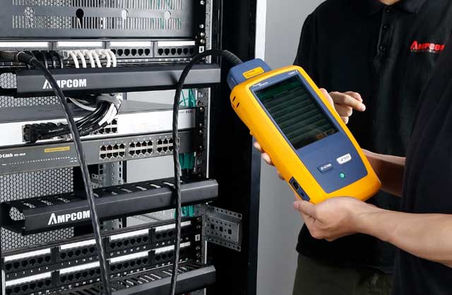
A cable certifier with shielded adapter is the only tool that can validate whether the shield provides actual EMI protection
8. Deployment Scenarios: Data Centers, Industrial, and Outdoor
Data Center High-Density Cat6A
In hyperscale and enterprise data centers, Cat6A STP is increasingly the default choice for 10GBASE-T copper links. The shield provides alien crosstalk (ANEXT) margin that allows denser cable bundles without performance degradation. Ground at the patch panel side only, bond the rack to the TGB, and use shielded patch panels with integral bonding strips. In environments with AI infrastructure cabling requirements, where cable density is extreme and EMI from adjacent high-power GPU racks is significant, STP's additional shielding is not optional — it is a design requirement.
Industrial Automation and Factory Floors
Factory environments with VFDs, welding equipment, and large motors generate some of the most aggressive EMI in any networking context. S/FTP cable is the standard choice here, with its braided shield providing low-frequency protection that foil alone cannot match. Industrial M12 connectors maintain shield continuity in vibration-heavy environments where standard RJ45 connections would fail. Ground at the control cabinet side, and use indoor/outdoor rated cable for any runs that cross environmental boundaries.
Outdoor and Security Networks
Outdoor STP installations face two additional challenges: surge protection and weatherproofing. Use GDT-equipped surge protectors at building entry points to clamp lightning and ESD events while maintaining shield isolation under normal conditions. Ensure all outdoor connectors are rated for UV exposure and moisture ingress. The shield should be grounded at the building entry point, with the far end isolated to prevent ground loops through the earth.
For extended cable runs using inline couplers, verify that the couplers are shielded and maintain drain wire continuity. A single unshielded coupler in a 100-meter run negates the entire shield system.
Migration Strategy: UTP to STP
If you are upgrading an existing UTP infrastructure to STP, do not attempt a piecemeal approach. Mixing shielded and unshielded components in the same channel — even temporarily — creates the worst-case scenario: a shield that floats and collects noise with no path to ground. Plan the migration in complete link segments: replace the cable, connectors, keystone jacks, and patch panel for an entire link at the same time. Test and certify each link before moving active equipment to it. This approach is more labor-intensive but eliminates the intermittent failures that plague partial migrations.
Also consider whether migration is actually necessary. If your existing UTP installation passes certification and the environment has not introduced new EMI sources, the cost and risk of migration may not be justified. For guidance on when to stay with UTP, see this analysis of Ethernet cable options and wire gauge considerations for PoE runs.
Key Questions (FAQ)
Q1: What happens if you don't ground STP cables?
An ungrounded shield acts as an antenna, collecting electromagnetic interference and redistributing it along the entire cable run. Network performance in this scenario can be worse than using unshielded UTP cable in the same environment. Common symptoms include intermittent connectivity, unexplained packet loss, and inconsistent throughput under load. The shield must be connected to a stable ground reference to function as a Faraday cage that safely diverts EMI away from signal conductors.
Q2: Should STP cable shields be grounded at one end or both ends?
Single-end grounding at the patch panel or equipment rack side is the established best practice for most commercial and enterprise installations. Grounding at only one end prevents ground loops caused by potential differences between two grounding points. Double-end grounding can drive objectionable current through the shield, which couples noise into data lines and causes errors, dropped packets, and equipment stress. For outdoor or long cable runs where surge protection is needed, gas discharge tube (GDT) surge protectors maintain isolation under normal conditions while clamping dangerous transient energy during lightning or ESD events.
Q3: Can I mix shielded and unshielded components in the same channel?
Mixing shielded cable with unshielded connectors, keystone jacks, or patch panels breaks shield continuity and eliminates the EMI protection the shield was designed to provide. This is one of the most common and dangerous installation errors. A shielded channel must maintain end-to-end shielding: shielded cable, shielded RJ45 connectors, shielded keystone jacks, and shielded patch panels. If any component in the chain is unshielded, the entire link degrades to unshielded performance or worse, because the floating shield can act as an antenna.
Q4: What is the correct bend radius for STP cable installation?
The general rule for STP cable bend radius is 10 times the cable's outside diameter for permanent installations and 6 times for patch cords during installation. For a typical Cat6A shielded cable with an outside diameter of approximately 7.5mm, the minimum bend radius is about 75mm (3 inches) for permanent runs. Exceeding the bend radius crushes the shield, deforms the twisted pair geometry, and increases both crosstalk and attenuation. Always follow the cable manufacturer's published specifications, as they may vary by product.
Q5: How far should STP cables be from power lines?
Maintain at least 300mm (12 inches) of separation from power lines carrying up to 480V, and increase separation for higher voltages. When crossings are unavoidable, route communication cables perpendicular to power lines rather than parallel. In metal conduit, separation can be reduced but should still follow TIA-569 and NEC guidelines. Shielded cable helps mitigate residual coupling, but physical separation remains the primary defense against inductive noise from adjacent power conductors.
Q6: What standards govern STP cable grounding?
Key standards include TIA-568 (commercial building telecommunications cabling), TIA-607 (telecommunications grounding and bonding), ISO/IEC 11801 (information technology cabling), and NEC Article 250 (grounding and bonding, NFPA 70 2023 edition). TIA-607 defines the telecommunications grounding busbar (TGMB) and telecommunications grounding backbone (TGBB) framework that bonds equipment racks and patch panels to the building's main grounding system. BICSI also provides installation best practices complementary to these standards.
Q7: How do I test shield continuity after installation?
Use a cable certifier with shield continuity testing capability, such as a Fluke DSX series tester with the appropriate shielded adapter. The test verifies that the shield maintains electrical continuity from one end of the link to the other. Basic tone-and-probe tools cannot validate shield performance. After continuity verification, also test for ground loops by measuring potential difference at both ends before connecting equipment. Run full certification tests including wiremap, NEXT, return loss, and attenuation to ensure the complete channel meets the specified category performance.
Q8: Is STP cable necessary for Cat6A data center deployments?
Both UTP and STP Cat6A can support 10GBASE-T at full 100-meter channels when correctly installed. STP is preferred in high-density data center environments where alien crosstalk from adjacent bundles is a concern, as the shield provides additional ANEXT margin. The decision depends on cable routing density, proximity to EMI sources, and the building's grounding quality. If the facility lacks a clean, properly bonded ground system, a well-installed UTP system may outperform an improperly grounded STP system.
About AMPCOM
AMPCOM engineers a complete portfolio of shielded copper connectivity solutions for data center, enterprise, and industrial environments. Our Tough Armor S/FTP patch cables combine braided and foil shielding for maximum EMI protection, while our Cat6A shielded network cables deliver 10GBASE-T performance with ANEXT margin for high-density deployments. We also supply shielded tool-less RJ45 connectors, shielded keystone jacks, and shielded patch panels with integral bonding strips — ensuring end-to-end shield continuity across your entire channel. Every shielded assembly ships with category compliance documentation and termination instructions.
Related Articles
- STP Grounding Best Practices — Foundational principles of shielded cable grounding and bonding
-
Do You Really Need to Ground STP Cables? — Addressing the most debated question in shielded cabling
- Shielded vs. Unshielded Patch Panels: Grounding — How patch panel selection affects grounding architecture
-
Alien Crosstalk Mitigation for Cat6A — Why STP shields matter in dense cable bundles

AMPCOM Technical Team
Industry experts with 17+ years in enterprise network infrastructure and structured cabling systems
Need help with your shielded cabling project?
Our technical team provides free consultation on STP cable selection, grounding architecture, and installation best practices for data centers, industrial facilities, and enterprise networks.
Get Free Expert Consultation

