Fiber Optic Pigtail: The Complete Guide to Types, Splicing Methods & Real-World Applications
Published:Executive Summary: A fiber optic pigtail is one of the most commonly specified yet least understood components in structured cabling. Get the wrong connector type, the wrong polish, or skip proper fusion splicing technique—and you're looking at elevated signal loss, increased back reflection, and a field termination that fails certification. This guide covers everything: what fiber optic pigtails are, how they differ from patch cords, which connector and polish type to specify, how to choose between mechanical and fusion splicing, and the real-world applications where pigtails are the right call.
Whether you're building out an ODF (optical distribution frame) in a hyperscale data center or terminating FTTH drop cables in the field, the decisions you make about your fiber pigtails directly affect long-term network performance and reliability.
Quick Navigation
- 1 What Is a Fiber Optic Pigtail?
- 2 Fiber Pigtail vs. Fiber Patch Cord: Key Differences
- 3 Types of Fiber Optic Pigtails
- 4 Connector Types: LC, SC, FC, ST Explained
- 5 Polish Types: PC vs UPC vs APC
- 6 Splicing Methods: Fusion vs. Mechanical
- 7 Real-World Applications
- 8 Installation Best Practices
- 9 How to Choose the Right Fiber Pigtail
- 10 Key Questions Answered
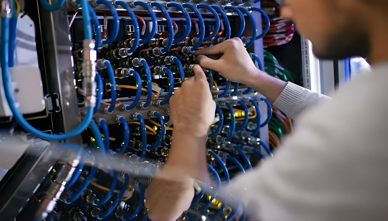
Fiber optic pigtails are the backbone of reliable field termination in enterprise networks, data centers, and telecom infrastructure
There's a moment every network installer knows well: you're standing in a telecom room with a bundle of bare fiber and a deadline, and you need to terminate it properly—fast, reliably, and without rework. That's exactly the scenario where fiber optic pigtails were designed to excel.
Fiber pigtails are used in an estimated 99% of single-mode fiber applications worldwide. Despite this ubiquity, they remain a source of confusion for procurement teams and junior installers alike—especially when it comes to connector type selection, polish type, and the tradeoffs between mechanical and fusion splicing.
This guide resolves all of that. Let's start at the beginning.
1. What Is a Fiber Optic Pigtail?
A fiber optic pigtail is a short length of optical fiber cable with a factory-terminated connector on one end and a bare, exposed fiber on the other. Unlike a patch cord—which has connectors on both ends—the bare fiber end of a pigtail is designed to be permanently spliced (either by fusion or mechanical splicing) to the incoming fiber cable in the field.
The connector end plugs directly into active equipment, an ODF port, or a fiber splice tray, while the bare fiber end creates a low-loss permanent joint with the incoming cable. This design gives you the best of both worlds: the precision and consistency of a factory-manufactured connector with the flexibility of custom-length field splicing.

A fiber optic pigtail: factory-terminated connector on one end, bare fiber ready for splicing on the other
In practical terms, pigtails show up in several key places:
- Inside optical distribution frames (ODFs) and fiber terminal boxes, where incoming cable is spliced to pigtails and the connector ends populate a patch panel
- In fiber splice enclosures at building entry points, outdoor pedestals, and underground vaults
- At any point where you need to transition from a bulk fiber cable to a connectorized, pluggable interface
Why Not Just Use a Patch Cord?
Patch cords have connectors on both ends, which is great for connecting two already-terminated devices. But when you're working with bulk cable runs—a 200-meter reel of OS2 fiber entering a building from a buried conduit, for example—you can't simply plug a patch cord into the end. You need to splice, and a pigtail is the cleanest, most reliable way to make that transition.
2. Fiber Pigtail vs. Fiber Patch Cord: Key Differences
These two components are closely related—in fact, you can cut a patch cord in half to produce two pigtails—but they serve fundamentally different roles in a network. Understanding the distinction prevents costly spec errors.
| Feature | Fiber Optic Pigtail | Fiber Patch Cord |
|---|---|---|
| Connectors | One end only (factory-terminated) | Both ends (factory-terminated) |
| Other End | Bare fiber — spliced in the field | Connector — plugs directly into equipment |
| Primary Use Case | Terminating bulk fiber cable runs; ODF/splice tray population | Connecting two already-terminated devices or ports |
| Connection Type | Permanent (spliced) | Temporary or semi-permanent (pluggable) |
| Jacket | Typically unjacketed (protected by splice tray) | Jacketed — LSZH, ONFR, ONFP, PVC |
| Best Environment | Splice enclosures, ODF panels, terminal boxes | Equipment racks, patch panels, server connections |
| Typical Length | 0.5m – 3m | 0.5m – 30m+ |
| Relationship | One fiber patch cord = two fiber pigtails (cut in half) | |
One installer trick worth knowing: if you need pigtails in the field and only have patch cords available, you can cut a tested, certified patch cord down the middle to produce two pigtails. You already know the connector end-face quality is good (the factory tested it), so you only need to verify the splice performance after the fact.
3. Types of Fiber Optic Pigtails
3.1 By Fiber Type: Singlemode vs. Multimode
The fiber type is often your first decision—and it's driven by your existing network infrastructure and application requirements, not personal preference.
| Fiber Type | Fiber Specification | Max Transmission Distance | Typical Application | Jacket Color |
|---|---|---|---|---|
| Singlemode OS2 | 9/125 µm core | Up to 4 km (and beyond with amplification) | Backbone fiber, campus networks, FTTH, long-haul WAN | Yellow |
| Multimode OM1 | 62.5/125 µm core | Up to 275m (1G), 33m (10G) | Legacy LAN systems | Orange |
| Multimode OM2 | 50/125 µm core | Up to 550m (1G), 82m (10G) | Short-range LAN, storage networks | Orange |
| Multimode OM3 | 50/125 µm core | Up to 300m (10G), 70m (40/100G) | Data centers, enterprise LAN | Aqua |
| Multimode OM4 | 50/125 µm core | Up to 400m (10G), 150m (40/100G) | High-density data centers, 40G/100G links | Aqua or Violet |
| Multimode OM5 | 50/125 µm core (WBMMF) | Up to 150m (100G), supports SWDM4 | Next-gen data centers, 400G+ links | Lime Green |
Pro Tip: Always Match Fiber Type Across the Link
Mixing singlemode and multimode pigtails in the same link is a common and costly mistake. The core diameters (9 µm vs. 50–62.5 µm) are fundamentally incompatible—attempting to splice or connect them results in massive insertion loss (often 10+ dB) that will fail every optical power budget test. Always confirm your existing infrastructure before ordering pigtails.
3.2 By Fiber Count
Fiber optic pigtails are available in single-fiber and multi-fiber configurations. Common fiber counts include 1, 2, 4, 6, 8, 12, 24, 48, and 72 fibers. Multi-fiber pigtails use color-coded individual fibers per the TIA-EIA-598-A color standard, which allows technicians to identify and trace individual fibers within a bundle quickly and accurately.
For most enterprise termination work, single-core pigtails are the standard choice. Multi-fiber pigtail bundles are more common in high-density ODF installations and data center applications where dozens or hundreds of fibers need to be terminated in a single panel.
3.3 By Environment: Indoor, Armored, and Waterproof
- Indoor pigtails: The most common type. Lightweight, flexible, no extra protective layer. Designed for protected environments like splice trays inside ODF panels, fiber terminal boxes, and distribution frames. Not suitable for direct exposure to moisture, UV, or mechanical stress.
- Armored pigtails: Feature an additional metal protective layer around the fiber. More durable against crushing and accidental impact. The right choice for installations where the pigtail may be exposed to physical abuse—industrial telecom rooms, outdoor-access panels, or anywhere with high foot traffic near cable management.
- Waterproof pigtails: Built with stainless steel armored PE sheathing and waterproof connector housings. Low insertion loss, high return loss, corrosion-resistant. Used in CATV field installations, outdoor splice closures, and military/industrial applications where moisture ingress is a real concern.
4. Connector Types: LC, SC, FC & ST Explained
The connector type you choose must match the equipment interface on the other end of the link. Here's a practical breakdown of the four most common pigtail connector types.
| Connector | Full Name | Ferrule Size | Best For | Key Characteristic |
|---|---|---|---|---|
| LC | Lucent Connector | 1.25 mm ceramic | High-density data centers, enterprise LANs, SFP transceivers | Half the footprint of SC — preferred for high-density patch panels and transceivers |
| SC | Subscriber Connector | 2.5 mm ceramic | Telecom networks, FTTX, ISP access networks, PON infrastructure | Push-pull locking — easy to operate in low-light environments; widely used by ISPs |
| FC | Ferrule Connector | 2.5 mm ceramic | Test equipment, DWDM systems, environments requiring vibration resistance | Screw-type threaded coupling — excellent for vibration-prone environments |
| ST | Straight Tip | 2.5 mm ceramic | Legacy multimode LAN, industrial networks, building security systems | Bayonet-style locking — once the most common multimode connector; being superseded by LC |
In practice, LC has become the dominant connector type for new enterprise and data center deployments due to its compact 1.25mm ferrule and push-latch mechanism. You can fit twice as many LC ports as SC ports in the same panel footprint, which makes a measurable difference when you're managing hundreds of connections in a single rack.
SC remains the connector of choice for access network and FTTX deployments, where the larger, robust push-pull mechanism is easier to operate in field conditions and the existing installed base of SC-compatible equipment is enormous.

LC, SC, FC, and ST connector types each have specific strengths — match connector type to your equipment and environment
5. Polish Types: PC vs UPC vs APC — Which One Do You Need?
Beyond the connector type, every fiber pigtail connector end-face is polished to a specific geometry. This polish type directly affects insertion loss and return loss (back reflection)—two specs that matter enormously for signal integrity in sensitive optical systems.
| Polish Type | End-Face Geometry | Return Loss | Typical Use Cases | Notes |
|---|---|---|---|---|
| PC (Physical Contact) | Slightly curved (radius ~25mm) | ≥ 40 dB | Legacy multimode LANs | Largely replaced by UPC in new installations |
| UPC (Ultra Physical Contact) | More curved, smoother finish | ≥ 50 dB | Singlemode & multimode LANs, data centers, enterprise networks | Most common polish type in new deployments; blue connector body |
| APC (Angled Physical Contact) | 8-degree angled grind | ≥ 60 dB | CATV, FTTX/PON networks, DWDM, wavelength-sensitive systems | The 8° angle reflects back-light away from the fiber core; green connector body |
UPC vs APC: The Decision That Trips Most People Up
Choose UPC when: You're building or expanding an enterprise LAN, data center interconnect, or standard singlemode backbone. UPC delivers excellent return loss (≥50 dB) suitable for the vast majority of digital data applications.
Choose APC when: Your system is sensitive to back reflection—specifically CATV analog video, PON/FTTX deployments, or DWDM wavelength-division multiplexing systems. The 8-degree angled polish scatters back-reflected light away from the fiber core, giving you ≥60 dB return loss. This matters in analog optical systems where reflected light causes signal degradation that you won't see on a simple OTDR trace but will absolutely hear in video quality.
Critical warning: APC and UPC connectors are physically incompatible—you should never mate an APC connector with a UPC counterpart. Doing so will damage the polished end-faces of both connectors and introduce significant insertion loss. APC connectors have green housings and a slightly angled ferrule face specifically to prevent accidental mating with UPC (blue or beige) connectors.
6. Splicing Methods: Fusion vs. Mechanical
Once you've selected your pigtail, the bare fiber end needs to be permanently joined to the incoming cable fiber. You have two methods: fusion splicing and mechanical splicing. The right choice depends on your performance requirements, budget, and the volume of splices you're performing.
6.1 Fusion Splicing
Fusion splicing uses a precision arc discharge between two electrode rods to heat and fuse the cleaved fiber ends together. When done correctly, the splice point becomes essentially seamless—the glass of the two fibers melts together into a single, continuous strand. A properly executed fusion splice has an insertion loss of just 0.01–0.05 dB and virtually no back reflection.
This is the gold standard for permanent fiber connections, and it's why fusion splicing is specified for backbone fiber runs, long-haul telecom networks, and any application where link budget is tight. The tradeoff is upfront investment—a quality fusion splicer costs $1,500–$8,000+ depending on the model—but the cost per splice is low once you have the machine, making it cost-effective at scale.
6.2 Mechanical Splicing
Mechanical splicing uses a precision alignment sleeve filled with index-matching gel to hold two cleaved fiber ends in physical contact. No heat is applied—the fibers are simply aligned and clamped. Installation is faster than fusion splicing and requires no expensive splicer machine, making it attractive for small-volume work, emergency repairs, or situations where a fusion splicer isn't available.
The tradeoff is performance: mechanical splices typically introduce 0.20–0.50 dB of insertion loss and higher back reflection than fusion splices. For most indoor LAN applications, this is acceptable. For long-haul singlemode links with tight power budgets, it may push you past margin.
| Criterion | Fusion Splicing | Mechanical Splicing |
|---|---|---|
| Typical Insertion Loss | 0.01 – 0.05 dB | 0.20 – 0.50 dB |
| Back Reflection | Very low (virtually seamless joint) | Higher (gel-aided contact) |
| Initial Investment | High ($1,500–$8,000+ for splicer) | Low (hand tools only) |
| Cost per Splice | Low (consumables only) | Higher (sleeves ~$1–3 each) |
| Installation Speed | 2–5 minutes per splice | 1–3 minutes per splice |
| Joint Permanence | Permanent (glass fused) | Semi-permanent (mechanical hold) |
| Best For | Backbone fiber, long-haul, singlemode, large-scale projects | Emergency repairs, small-volume work, temporary connections |
When the Choice Is Clear
If you're deploying more than 20–30 pigtail splices on a project, the math almost always favors fusion splicing. The splicer pays for itself in saved rework time alone. If you're doing 2–3 emergency field repairs with no splicer available, mechanical splicing is the right answer—just document the insertion loss and verify you're still within the link's power budget.
7. Real-World Applications of Fiber Optic Pigtails
Fiber optic pigtails show up across virtually every segment of modern network infrastructure. Here's where they're most commonly specified—and why.
7.1 Data Centers
In hyperscale and enterprise data centers, pigtails are used to populate ODF panels and fiber splice trays, creating the connectorized interfaces between backbone cable runs and the patch panel ports used for daily moves, adds, and changes. The combination of OM4 or OM5 multimode pigtails (for within-rack and within-row links) and OS2 singlemode pigtails (for inter-building and long-reach connections) covers virtually all data center fiber termination needs. High-density applications use LC pigtails almost exclusively to maximize port density in 1U and 2U panel footprints.
7.2 Telecom and Access Networks
In outside plant (OSP) and access network deployments, SC/APC pigtails are the dominant choice for PON (Passive Optical Network) FTTX infrastructure. The APC polish type is essential here because the analog RF video signals still present in many CATV-over-fiber systems are highly sensitive to back reflection. A street-level fiber splitter cabinet or a building entry point might contain dozens of SC/APC pigtails, each fusion-spliced to a distribution fiber and populating the splitter's output ports.
7.3 Enterprise Campus Networks
Campus backbone runs—the OS2 singlemode cables connecting buildings, IDF closets, and MDFs—are almost always terminated using fiber pigtails at each end, with the pigtail spliced to the cable inside a wall-mounted fiber enclosure or ODF. The connector ends populate patch panel ports, where patch cords then connect to network switches. This approach gives you maximum flexibility: the backbone cable is permanent, but the connector-side of the link is fully rearrangeable with standard patch cords.
7.4 Industrial and Special Environments
Factory automation networks, oil and gas facilities, smart grid infrastructure, and military communications systems all use specialized pigtails—armored designs for crush and impact resistance, waterproof designs for outdoor and underground environments, and in some cases FC connectors for vibration-prone settings where a threaded coupling outperforms push-latch designs.
8. Installation Best Practices
Even the highest-quality fiber optic pigtail delivers poor performance if it's improperly installed. These best practices apply to every pigtail deployment.
✅ Do This
- Clean the connector end-face with an IEC-61300-3-35-compliant cleaner before every mating—even brand-new connectors ship with contamination
- Inspect the end-face with a 200–400× fiber microscope before plugging in; reject any connector showing scratches, pits, or contamination in the core area
- Store unused pigtails with dust caps installed on the connector end and a loose protective wrap on the bare fiber end
- Route and coil pigtail bare-fiber ends gently inside the splice tray, maintaining the minimum bend radius specified by the manufacturer
- Label both the connector end and the splice point immediately after installation—don't rely on memory
- Perform OTDR testing and optical power meter testing after splicing to verify insertion loss is within spec before closing the splice enclosure
❌ Avoid This
- Don't overfill splice sleeves when installing them into the splice case—overcrowding causes micro-bends that increase attenuation
- Don't exceed the manufacturer's minimum bend radius—even brief sharp bends during installation can cause permanent microfractures in the glass fiber
- Don't touch the polished end-face with your fingers—skin oils are one of the most common sources of end-face contamination
- Don't mix APC and UPC connectors—physical damage to both end-faces is guaranteed
- Don't install indoor-rated pigtails in wet, outdoor, or UV-exposed environments—use armored or waterproof designs instead
- Don't skip end-face inspection—contamination is invisible to the naked eye and accounts for the majority of fiber link failures
9. How to Choose the Right Fiber Optic Pigtail
Use this decision framework to specify the correct pigtail for any application. Every selection decision should start with the network's existing infrastructure and work outward to the specific product spec.
Fiber Pigtail Selection Checklist
Step 1 — Match your fiber type: Is the existing infrastructure singlemode (OS2, yellow) or multimode (OM3/OM4, aqua; OM4/OM5, violet/lime)? The pigtail fiber must match exactly.
Step 2 — Select the connector type: What connector does your ODF panel, fiber enclosure, or active equipment require? LC for data center/enterprise, SC for telecom/FTTX, FC for test equipment/DWDM, ST for legacy multimode LAN.
Step 3 — Determine polish type: Standard digital data applications → UPC. Analog video (CATV), PON/FTTX, or wavelength-sensitive systems → APC. Never mix the two in the same link.
Step 4 — Choose the environment rating: Protected indoor splice tray → standard indoor pigtail. Mechanical stress, accidental impact risk → armored. Outdoor, underground, or CATV field cabinet → waterproof armored.
Step 5 — Verify fiber count: Single fiber for point-to-point links. Multi-fiber bundles (6, 12, 24+) for mass-termination of multi-fiber backbone cables.
Step 6 — Select splicing method: Large project, permanent link, performance-critical → invest in fusion splicing. Emergency repair, low-volume, non-critical → mechanical splicing is acceptable with documented loss verification.
10. Key Questions Answered: Fiber Optic Pigtail
Common Questions, Straight Answers
Conclusion: Pigtails Are Simple. Getting Them Right Isn't.
Fiber optic pigtails are elegantly simple components—a connector on one end, bare fiber on the other. But the decisions that go into specifying them correctly (fiber type, connector type, polish, environment rating, splicing method) have direct consequences for network performance, link budget, and long-term reliability.
Get the connector type right, and your ODF ports populate cleanly. Specify APC where APC is required, and your PON system runs without the back-reflection noise that degrades video and increases bit error rates. Invest in fusion splicing for high-volume production work, and your long-haul links have the loss margin to accommodate future growth. These aren't theoretical concerns—they're the day-to-day realities that experienced network designers factor into every fiber termination spec.
AMPCOM's fiber pigtail range covers every scenario described in this guide: singlemode OS2 and multimode OM3/OM4, LC and SC connectors, UPC and APC polish, indoor and armored variants—all manufactured to IEC standards and ISO 9001 quality protocols.
Related Articles
- How to Choose the Right Fiber Type: Singlemode vs Multimode — OM3/OM4 vs OS2: matching fiber type to link speed and distance.
- MPO Fiber Solutions for Data Center and High-Density Cabling — Selecting the right MPO configuration for your deployment.
- How AI Infrastructure Is Reshaping Data Center Cabling Requirements — Understanding the unique demands of AI workloads on network infrastructure.

AMPCOM Technical Team
Structured Cabling Experts · 17+ years in enterprise fiber infrastructure
Need Fiber Pigtails for Your Next Project?
AMPCOM offers a full range of factory-tested fiber optic pigtails for data centers, telecom networks, campus infrastructure, and industrial deployments. Free consultation available for enterprise projects.
Get Free Consultation

