
Liquid Cooling Meets Structured Cabling: Material Compatibility, Routing Design, and Sealing Solutions for 30kW–120kW Racks
Published:Executive Summary: The AI compute revolution has pushed data center rack power densities to 30kW–120kW+, making liquid cooling no longer optional — it's mandatory. But what happens to your structured cabling when you introduce dielectric fluids, cold plate manifolds, and sealed tank boundaries? This article examines the material compatibility, routing design, and sealing solutions that every cabling engineer needs to understand before specifying infrastructure for liquid-cooled AI clusters.
Quick Navigation

High-density AI data centers demand liquid cooling — and the cabling infrastructure must adapt accordingly
Chapter 1: Why Liquid Cooling Changes Everything for Cabling
The AI compute revolution has pushed data center rack power densities far beyond what traditional air cooling can handle:
| Deployment Type | Typical Rack Power | Cooling Method |
|---|---|---|
| Standard enterprise (2024) | 8–15 kW | Air cooling (hot/cold aisle) |
| AI training (2026 mainstream) | 30–60 kW | Cold plate liquid cooling |
| Leading-edge AI (2026) | 80–120 kW | Immersion cooling (single/two-phase) |
| Next-gen forecast (2028) | 150 kW–1.5 MW | Two-phase immersion + facility-level |
Google's TPU v7 chips consume 980W each and mandate 100% liquid cooling. This thermal paradigm shift has a direct and often overlooked impact on the cabling infrastructure running through and around these racks.
When you introduce liquid coolant — whether in cold plates attached to chips or as a full-immersion bath — your cabling system faces three new challenges:
- Chemical compatibility: Will cable jacket materials withstand prolonged contact with coolant fluids?
- Temperature cycling: Can connectors and fibers maintain optical performance across wider temperature ranges?
- Sealing and ingress protection: How do you route cables through coolant containment boundaries without leaks?
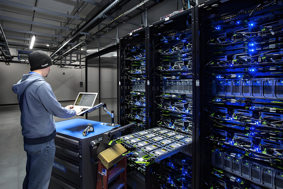
AI training clusters demand extreme power densities — and cabling must operate reliably alongside liquid cooling systems
Key Question
Q: Does liquid cooling really affect cabling that much? Isn't it just the server internals?
A: It depends on the cooling approach. Cold plate liquid cooling has minimal direct impact on external cabling — coolant stays in sealed plates and pipes. But immersion cooling fundamentally changes the environment: all cabling within the tank is submerged in dielectric fluid, requiring jacket materials rated for continuous fluid exposure. Even in cold plate systems, the higher ambient temperatures and the presence of coolant piping require careful cable routing and separation planning. For background on how these requirements fit into the bigger picture, see Structured Cabling for AI Data Centers: What Is Changing.
Chapter 2: Cold Plate Cooling — Cabling Considerations
How Cold Plate Systems Work
Cold plate systems attach liquid-cooled plates directly to CPUs, GPUs, and ASIC chips. Coolant (typically water-glycol mixture) circulates through the plates, carrying heat to a Coolant Distribution Unit (CDU), which rejects heat to the building's chilled water system or a dry cooler.
In this architecture, the cabling outside the server (fiber jumpers, copper patch cords, trunk cables) operates in a conventional air-cooled aisle environment. However, there are still important considerations:
Cable Routing Around Coolant Manifolds
- Maintain separation: Fiber optic cables should maintain a minimum 50mm clearance from coolant supply and return manifolds to prevent heat soak and condensation
- Use designated cable pathways: Don't route cables through or across cold plate piping runs — use overhead or under-floor cable trays with physical barriers
- Plan for maintenance access: Cold plate systems require periodic inspection and connector tightening. Ensure cable routing doesn't block access to quick-disconnect fittings
Higher Ambient Temperatures
Cold plate systems reduce server exhaust temperatures but the overall rack environment can run warmer than traditional air-cooled designs, since less air is moving through the rack. Ensure your cabling products are rated for up to 60°C continuous operation — standard PVC-jacketed cables typically have a 70°C rating, but verify the operating temperature range for your specific deployment. For a deep dive on jacket material differences, see PVC vs LSZH Ethernet Cable Jackets.
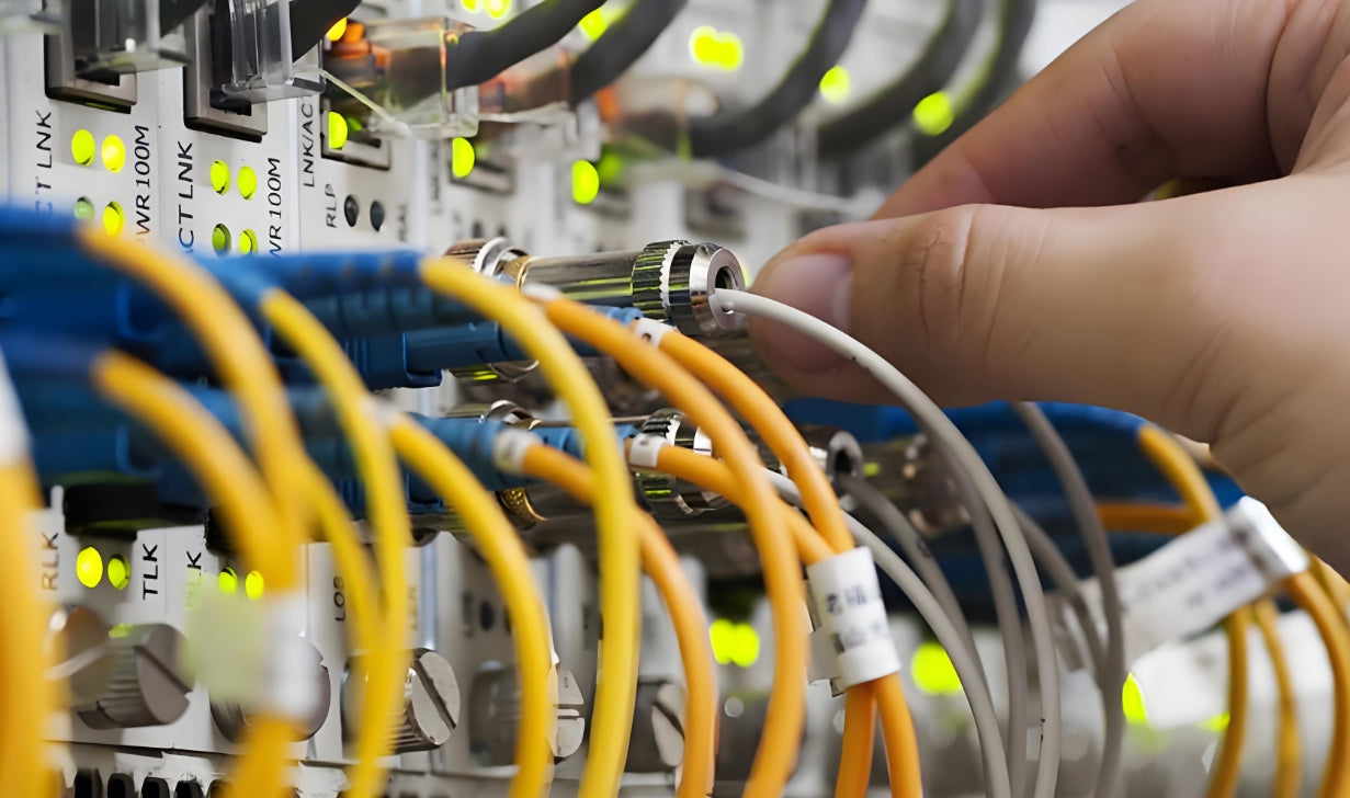
Even in cold plate environments, fiber cabling must maintain clearance from coolant manifolds and withstand higher ambient temperatures
AMPCOM Solutions for Cold Plate Environments
OS2 Single-Mode Fiber Patch Cables: LSZH jackets rated for -20°C to +70°C, suitable for elevated temperatures in cold plate-cooled racks
OM3/OM4/OM5 Multimode Assemblies: Factory-tested for consistent insertion loss in demanding thermal environments
Modular Patch Panels: High-density designs that accommodate tight cable routing around coolant infrastructure
Cat6A LSZH Patch Cables: Maintain signal integrity up to 70°C with superior flame resistance in enclosed rack environments
Key Question
Q: Can standard RJ45 patch cords handle the temperatures in a cold plate-cooled rack?
A: Standard Cat6A patch cords are generally fine — the rack ambient in cold plate systems rarely exceeds 45°C. However, for high-density GPU racks where exhaust temperatures may spike, consider AMPCOM's Cat6A LSZH patch cables which maintain signal integrity up to 70°C and provide better flame resistance in enclosed rack environments.
Chapter 3: Immersion Cooling — The Cabling Challenge
Two Types of Immersion Cooling
| Single-Phase | Two-Phase | |
|---|---|---|
| How it works | Servers submerged in dielectric fluid that stays liquid | Dielectric fluid boils at chip surface, vapor rises, condenses, returns |
| Fluid temperature | 30–45°C | 50–65°C |
| Temperature control | ±2°C | ±1.5°C |
| Cable exposure | Continuous fluid submersion | Continuous fluid submersion + vapor phase |
| Material requirements | Fluid-compatible jacket materials | Highest-grade fluid compatibility required |

Immersion cooling fundamentally changes the cabling environment — material selection becomes critical
The Critical Factor: Cable Jacket Compatibility
Not all cable jackets are immersion-safe. The dielectric fluids used in immersion cooling (synthetic hydrocarbons, fluorocarbons, or engineered dielectric fluids) can:
- Swell common jacket materials (PVC, standard LSZH), degrading mechanical protection
- Extract plasticizers from PVC, contaminating the coolant and causing cloudiness
- Degrade optical fiber coatings if the buffer tube is breached
- Attack connector ferrule bonding materials in submerged optical connectors
Immersion-Rated Cabling Requirements
| Component | Standard | Immersion-Rated |
|---|---|---|
| Outer jacket | PVC or LSZH | PE, PUR, or FEP (fluid-compatible) |
| Buffer tubes | PBT or stainless steel | PBT or stainless steel (generally adequate) |
| Connector boots | Rubber or standard plastic | Silicone or FEP — avoid rubber boots |
| Optical fiber | Standard 250μm coated | Standard inside buffer tubes; avoid exposed fiber segments |
| Testing | Standard IEC tests | Minimum 1,000 hours continuous immersion exposure |
Immersion-Specific Design Practices
- Minimize connections inside the tank: Use factory-terminated, sealed assemblies rather than field-terminated connections submerged in fluid
- Use sealed cable entry points: Cable glands rated for the specific dielectric fluid prevent fluid migration along cable jackets
- Plan for fluid draining during maintenance: Cable routing should allow fluid to drain from cable surfaces when servers are removed for service
- Specify long-life assemblies: Immersion environments accelerate aging — choose cables with proven immersion test data (minimum 1,000 hours continuous exposure)
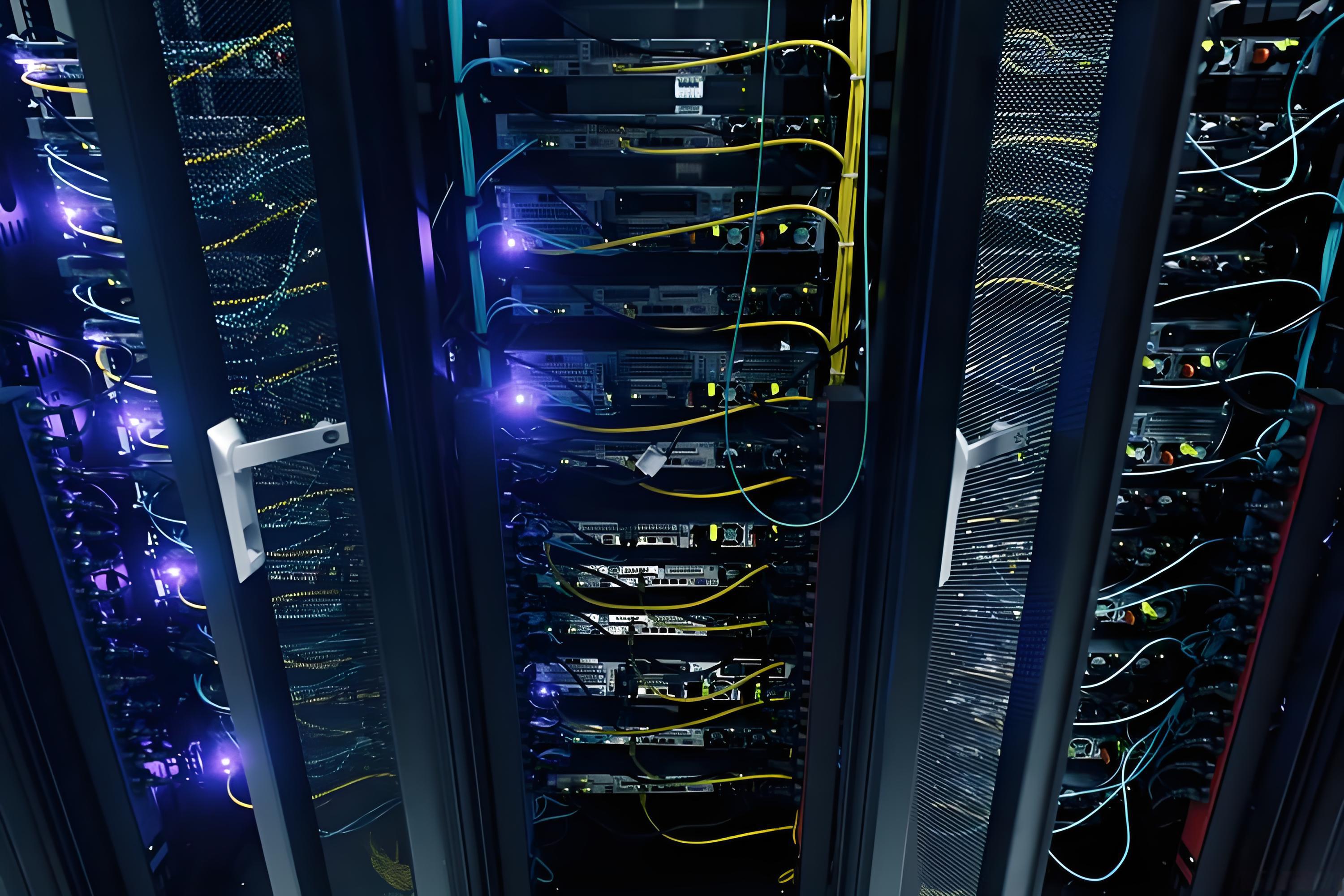
Fiber optic assemblies in immersion environments require purpose-built jacket materials and connector specifications
Key Question
Q: Can I use my existing fiber patch cables in an immersion-cooled tank?
A: Generally no. Standard PVC or LSZH patch cables are not rated for continuous immersion in dielectric fluid. The jacket material may swell, the boot materials may degrade, and plasticizer leaching can contaminate the coolant. You need purpose-built immersion-rated assemblies. AMPCOM can provide custom immersion-compatible fiber assemblies with verified fluid compatibility for your specific coolant type. For selecting the right fiber type for your application, see How to Choose the Right Fiber Type: Singlemode vs Multimode.
Chapter 4: Practical Cabling Architecture for Liquid-Cooled AI Clusters
Recommended Architecture: Zone Cabling with Transition Points
For AI training clusters using liquid cooling, we recommend a three-tier cabling architecture:
Three-Tier Liquid Cooling Cabling Architecture
Tier 1 — Spine / Core (Conventional Environment):
MPO trunk cables from spine switches to rack rows. Standard OS2/OM4/OM5 fiber and Cat6A/Cat8 copper operate normally in air-cooled spaces. See MPO Fiber Solutions for trunk configuration guidance.
Tier 2 — Transition Point (Tank Boundary):
IP68-rated cable glands or sealed bulkhead adapters maintain fluid containment at the tank penetration point. This is where standard cables meet immersion-rated cables.
Tier 3 — In-Tank Connections (Immersion Environment):
Short immersion-rated patch cables (1–3m per connection) from servers to top-of-rack switches. All connections must use fluid-compatible jacket and boot materials.
Key Design Principles
- Keep the longest runs outside the immersion environment: MPO trunk cables and interconnect cabling stay in conventional air-cooled spaces, where standard cabling is fully adequate
- Minimize immersion-submerged cable lengths: Only the rack-internal connections need immersion-rated cables — typically just 1–3 meters per connection
- Use sealed transition panels: At the tank boundary, use IP68-rated cable glands or sealed bulkhead adapters to maintain fluid containment
- Pre-terminate everything possible: In immersion environments, field termination is extremely difficult and unreliable. Factory-terminated assemblies are essential
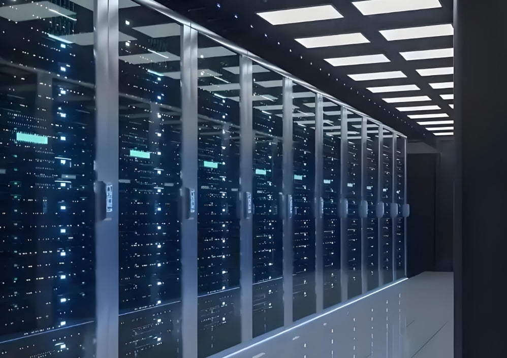
A well-architected cabling system separates conventional and immersion environments at sealed transition points
AMPCOM Solutions for Liquid-Cooled Data Centers
MPO/MTP Trunk Cables: For conventional-environment backbone runs supporting 800G/1.6T connectivity
Custom Immersion-Rated Fiber Patch Cables: Fluid-compatible jacket materials (PE/PUR/FEP) with sealed connectors
IP68-Rated Cable Glands & Bulkhead Adapters: For tank penetration points — maintaining sealed boundaries
High-Density Modular Patch Panels: Optimized for the tighter clearances in liquid-cooled rack environments
Pre-Sales Design Consultation: Optimize your cabling architecture for specific cooling technologies
Explore our full range: Fiber Optic Cable Types Guide and Strategic Fiber Selection.
Key Question
Q: We're retrofitting an existing data center from air cooling to cold plate liquid cooling. Do we need to replace our existing cabling?
A: In most cold plate retrofits, existing cabling can remain in place since the cooling change doesn't affect the external cable plant. However, you should: (1) verify that existing cables don't block cold plate manifold installation routes, (2) ensure cable ratings match the potentially higher operating temperatures, and (3) re-evaluate your cable management infrastructure for the modified rack layout. AMPCOM's engineering team can provide a site assessment to identify any required changes. For retrofit planning, also see When Should You Replace a Patch Panel Instead of Reorganizing It?
Conclusion
Liquid cooling — whether cold plate or immersion — is no longer optional for AI data centers operating at 30kW+ rack densities. For structured cabling, this means new requirements around material compatibility, temperature rating, sealing, and routing design. The good news: with the right product specifications and architectural approach, these challenges are manageable.
The key is to engage your cabling partner early in the design phase, specify immersion-rated materials where required, and leverage pre-terminated assemblies to ensure reliable performance in these demanding environments.
Related Articles
- 800G Is Not Just a Speed Upgrade — It Changes Which Fiber Designs Remain Manageable — Design considerations for 800G fiber infrastructure
- AI Data Center Cabling Is Getting Harder to Manage — What Actually Breaks First? — Identifying failure points in AI-scale cabling
- Why Fiber Optic Cabling is Key to Sustainable Data Center — Sustainability advantages of fiber infrastructure
- PVC vs LSZH Ethernet Cable Jackets: Safety, Smoke and Where Each Makes Sense — Understanding jacket material trade-offs

AMPCOM Technical Team
Industry experts with 15+ years in data center structured cabling and liquid cooling integration
Planning a liquid-cooled data center deployment?
Contact AMPCOM's technical team for a complimentary cabling design review and product specification consultation.
Get Free Consultation

