
High-Power PoE++ Cable Selection: How to Prevent Heat Buildup in Your Cabling Infrastructure
Published:Executive Summary: PoE++ (802.3bt, up to 90W per port) has become the de facto standard for powering Wi-Fi 7 access points, PTZ surveillance cameras, digital signage, and edge computing nodes — all over standard Ethernet cabling. Most engineers budget for bandwidth and calculate voltage drop. Far fewer treat cable selection as the thermal engineering problem it actually is. At 90W per port, Joule heating inside bundled cables can push conductor temperatures well beyond safe operating limits. This guide walks through the complete heat-thought cable selection process for 90W PoE++ deployments, from Joule's Law to field verification.
Quick Navigation
- 1 Why PoE++ Generates So Much More Heat Than Standard PoE
- 2 Cable Gauge: 23AWG vs 24AWG vs 28AWG
- 3 The Bundling Trap: TIA-568.1-D and Cable Derating
- 4 Small-Diameter Cat6A: Benefits and Hidden Pitfalls
- 5 Shielded vs Unshielded Cable for PoE++
- 6 Installation Best Practices Checklist
- 7 Field Verification: What to Test and Why
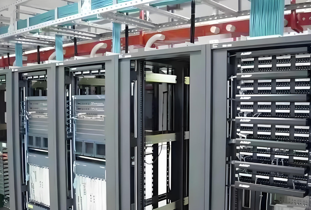
Heat buildup inside cable bundles is the primary cause of connection failures and premature cable degradation in 90W PoE++ deployments — and it is often overlooked
Chapter 1: Why PoE++ Generates So Much More Heat Than Standard PoE
The Joule Heating Problem
All current flowing through a conductor generates heat. This is Joule's First Law: P = I²R (power equals current squared times resistance). Unlike data signals at high frequency, DC PoE current flows continuously through all four wire pairs — at significantly higher amperages than most people realize.
Key insight: Heat scales with the square of current. A single 90W PoE++ connection produces roughly 34× more resistive heating in the same cable than a standard 15W PoE connection. That heat has nowhere to go inside a bundle.
What Happens When Cables Overheat?
- Connector failure: RJ45 contacts and IDC punchdown points are rated for specific temperature ranges. Sustained operation above 60°C accelerates metal migration and contact degradation.
- Insertion loss increase: Heat raises conductor resistance, increasing signal attenuation — particularly damaging for 10Gbps and above.
- Premature cable failure: Insulation materials (CM, CMR, CMP) have defined temperature ratings. Exceeding them accelerates polymer degradation and jacket brittleness.
- Safety risk: In plenum spaces, sustained overheating of incorrectly specified cables is a documented fire hazard.
The Bundling Multiplier Effect
The problem is not just one cable. When 12, 24, or 48 PoE++ cables run together in a bundle, the thermal load compounds. With no airflow inside the bundle center, temperatures can reach 20–30°C above ambient — well beyond safe operating limits for long-term deployments.
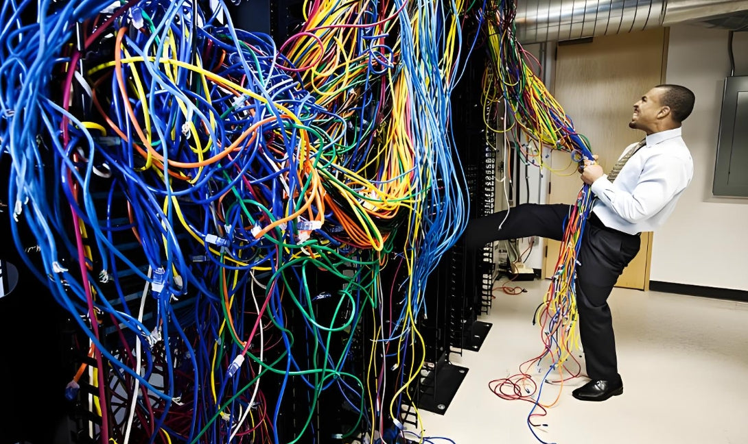
Heat accumulation in high-density PoE++ cable bundles is invisible — but its consequences (failed connections, premature aging) surface months later
Chapter 2: Cable Gauge — 23AWG vs 24AWG vs 28AWG
Why AWG Matters for Heat
American Wire Gauge (AWG) defines conductor diameter. Smaller gauge numbers = thicker conductors = lower DC resistance = less heat generated at the same current. For PoE++, AWG selection is not just about distance and voltage drop — it is a primary thermal design decision.
| Specification | 23AWG | 24AWG | 28AWG |
|---|---|---|---|
| Conductor diameter | 0.574 mm | 0.511 mm | 0.321 mm |
| DC resistance (per 100m, 20°C) | ~7.61Ω | ~9.38Ω | ~23.8Ω |
| Ampacity (max continuous current) | ~1.4A | ~1.2A | ~0.6A |
| Recommended max PoE load | 90W (Type 4) | 60W (Type 3) | 30W (PoE+) |
| Max recommended bundle at 90W | 16 cables | 6 cables | 2 cables |
| Best use case | Ideal for 90W | Acceptable | Short patch cords only |
23AWG: The Right Choice for PoE++
For 802.3bt Type 4 (90W) PoE++ deployments, 23AWG is the recommended minimum. Its lower resistance (7.61Ω/100m vs 9.38Ω for 24AWG) means significantly less heat generated per cable, which translates to safer bundle sizes and longer cable life.
For a deeper comparison of 23AWG vs 24AWG for voltage drop and long-run performance: 23 AWG vs 24 AWG Ethernet Cable: How Cable Gauge Impacts PoE, Voltage Drop & Long Runs
28AWG: A Special Case
28AWG stranded patch cords have a place — in short horizontal runs under 15m in well-ventilated racks. At 23.8Ω/100m, they generate substantial heat at PoE++ currents. For any run over 15m or in bundles, 28AWG is not suitable for PoE++. See: PoE Cabling Guide: Power Budget, Voltage Drop and 28AWG Trade-Offs
Chapter 3: The Bundling Trap — TIA-568.1-D and Cable Derating
The Standard That Changed Everything
The TIA-568.1-D standard introduced mandatory conductor temperature derating for bundled cables carrying PoE current. The core principle: as bundle size increases, the allowable current per conductor decreases because the thermal load compounds and central cables lose airflow access.
| Cables in Bundle | Derating Factor | 23AWG Safe Max Continuous Current |
|---|---|---|
| 1–7 | 1.00 (no derating) | ~1.4A |
| 8–19 | 0.82 | ~1.15A |
| 20–39 | 0.73 | ~1.02A |
| 40–59 | 0.68 | ~0.95A |
| 60+ | 0.62 | ~0.87A |
⚠️ The 90W Reality Check
At 90W (Type 4 PoE++), current per conductor is approximately 1.88A per pair. With a derating factor of 0.73 for a 20–39 cable bundle, 23AWG conductors can safely carry approximately 1.02A — well below the 1.88A required for 90W Type 4 PoE.
This means: in a 24-cable bundle, 90W PoE++ is not compliant with TIA-568.1-D on standard 23AWG cable without additional thermal management measures.
Practical Countermeasures
- Break bundles early: Route cables to separate pathways before bundle counts exceed safe thresholds.
- Separate by power tier: Keep 90W Type 4 cables in smaller bundles (8–12 max) while lower-power PoE/PoE+ cables can share larger bundles.
- Use vertical cable managers: Vertical managers provide airflow paths into horizontal bundles, reducing thermal buildup.
- Consider small-diameter Cat6A: Smaller OD cables improve inter-cable airflow, reducing thermal coupling between adjacent conductors.

In high-density data center PoE++ deployments, cable routing planning and bundle size control are critical for thermal management — this must be solved at the design stage, not after installation
Chapter 4: Small-Diameter Cat6A — Benefits and Hidden Pitfalls
The Case for Small-Diameter
Standard Cat6A cable has an outer diameter (OD) of approximately 6.0–7.0mm. Small-diameter Cat6A reduces this to 4.0–4.8mm. The benefit for PoE++ is clear: smaller OD = more space between cables = better airflow and faster heat dissipation within bundles.
📋 4 Things to Verify Before Specifying Small-Diameter Cat6A
- Patch panel and outlet compatibility: Small-diameter cables may not seat properly in standard keystone jack openings without adapter sleeves. Verify fitment with your specific hardware before bulk ordering.
- Pair-to-pair crosstalk (PSNEXT): Reducing cable OD sometimes requires tighter twist rates, which can degrade crosstalk performance. Verify the cable meets Category 6A PSNEXT requirements per TIA-568.2-D at full 100m.
- Mechanical durability: Smaller jackets offer less physical protection to the conductor assembly. Evaluate crush and impact specifications against your installation environment.
- PoE thermal rating: Confirm the cable is rated for conductor temperatures compatible with your PoE++ thermal load. Look for cables rated to 75°C or higher for Type 4 (90W) deployments.
For the full thermal limits of 28AWG under PoE++ loads: PoE++ on 28AWG: Thermal Limits, Safe Bundle Sizes, and Voltage-Drop Math You Can Trust
Chapter 5: Shielded vs Unshielded Cable for PoE++
The Thermal Advantage of Shielded Cable
The metallic shield in F/UTP or S/FTP cable acts as a secondary heat dissipation path. Because the shield makes physical contact with the overall cable assembly, it conducts heat away from the conductor core more effectively than UTP cable.
| Factor | Shielded (F/UTP / S/FTP) | Unshielded (U/UTP) |
|---|---|---|
| Heat dissipation path | Conductor + shield | Conductor only |
| EMI protection | Excellent | None |
| Grounding required | Yes (both ends) | No |
| Recommended for | Data centers, noisy environments | Standard office, low-EMI |
⚡ The Grounding Prerequisite
Shielded cable is only thermally and electrically effective if properly grounded at both ends. The drain wire must be connected to the patch panel ground bus bar and the switch chassis ground — reliably, and in compliance with local electrical codes. Improper grounding turns a shield into an antenna, not an asset.
Complete guide to shielded Ethernet grounding: STP Grounding Best Practices: Do You Really Need to Ground STP Cables?
The definitive PoE++ shielded vs unshielded decision guide: Do You Really Need Shielded Cable for PoE++? A Practical Guide for Cameras and Wi-Fi APs
Data Center vs Office Trade-Off
Data centers: Shielded Cat6A is almost always the right choice for PoE++. High cable density means the thermal advantage compounds, and the EMI environment benefits from the shielding.
Standard office environments: Unshielded Cat6A is typically sufficient for PoE/PoE+ and even PoE++ in lower-density deployments (fewer than 8 cables per bundle). Evaluate your specific EMI environment before specifying shielded.
Chapter 6: Installation Best Practices Checklist
6 Steps to a Thermally Safe PoE++ Deployment
🔧 Pre / During Installation Checklist
- Verify physical compatibility before pulling cable: Check that your cable OD fits: outlet keystone jacks, faceplate openings, patch panel ports, and cable management fingers.
- Plan bundle sizes before pulling — not after: Calculate the maximum number of PoE++ cables per bundle based on your AWG and TIA derating factors. For 23AWG Type 4 (90W): 8–12 cables per bundle maximum in static air conditions.
- Separate PoE power cables from data-only cables where feasible: Reduces thermal load per bundle and makes future troubleshooting easier.
- Never compress cables in cable managers: Tight Velcro wraps and over-tightened straps restrict airflow around conductors. Use轻轻 Velcro ties and maintain minimum bend radius (4× cable OD for Cat6A).
- Label everything with power tier specifications: Tag both ends of every PoE++ cable run with its power tier (Type 3 or Type 4) and wattage.
- Test with a Fluke Certifier after every installation: Certify the permanent link. For PoE++, verify DC resistance unbalance, which directly affects power delivery efficiency and thermal load distribution across pairs.
Detailed guide to reading Fluke test reports: How to Read Fluke Test Reports: A Priority Guide for Procurement
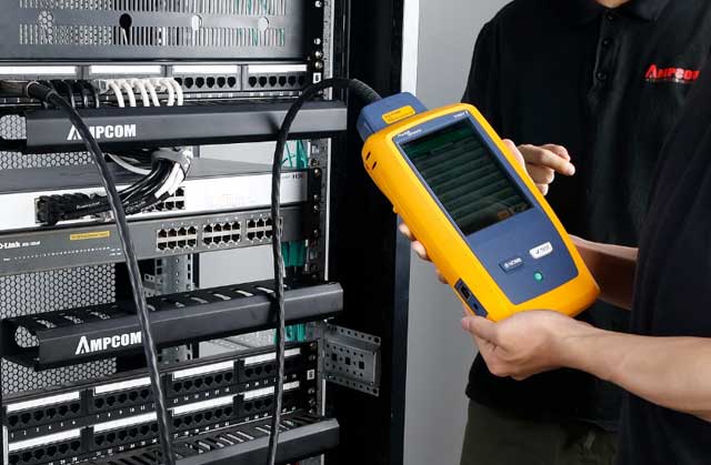
Using a Fluke certifier to verify PoE++ permanent links is the last line of defense to confirm that thermal design decisions remain effective post-deployment
Chapter 7: Field Verification — What to Test and Why
The Three Critical Tests for PoE++ Cabling
After installation, standard TIA channel certification is necessary but not sufficient for PoE++ deployments. Add these PoE-specific verifications:
| Test | What It Measures | Pass Criteria | Why It Matters for PoE++ |
|---|---|---|---|
| DC Resistance Unbalance | Resistance difference between wire pairs | ≤ 3% unbalance per pair | Unbalanced pairs cause unequal current sharing, creating localized hotspots |
| Conductor Temperature | Cable surface temp during powered operation | ≤ 60°C sustained | Directly validates thermal design decisions for bundle sizing |
| Insulation Resistance | Isolation between conductors and shield | ≥ 500MΩ per 100m | Degraded insulation = higher leakage current = additional resistive heat |
Interpreting Resistance Unbalance Results
High DC resistance unbalance (above 3%) means one pair carries more current than others, creating uneven thermal load. This is particularly problematic for PoE++ because power is split across all four pairs. A Fluke DSX-5000 or higher can measure resistance unbalance as part of an extended wiremap test.
For PoE-specific cable testing protocols: PoE Cabling for IP Cameras and Wi-Fi APs: Design Patterns for SMB Networks
Bottom Line
PoE++ deployment done right starts with understanding that cable selection is a thermal engineering problem, not just a connectivity problem.
The three decisions that determine your deployment's thermal safety:
1. Choose the right AWG for your power level.
23AWG for 90W Type 4. 24AWG minimum for 60W Type 3. Never use 28AWG in bundles for high-power PoE++.
2. Treat bundle size as a thermal design parameter.
Reference TIA-568.1-D derating tables. Plan bundle sizes before pulling cable. Separate 90W Type 4 cables into smaller bundles than lower-power runs.
3. Choose shielded cable for dense/high-EMI data center deployments.
The shield's thermal dissipation advantage compounds at high cable density. Ensure proper grounding on both ends.

AMPCOM Technical Team
Industry experts with 17+ years in structured cabling, data center infrastructure, and fiber optic network design
Need help choosing the right PoE++ cables for your data center?
AMPCOM provides a full range of Cat6A (23AWG, 24AWG, and small-diameter), shielded and unshielded patch cables, and keystone jacks rated for PoE++ up to 90W.
Talk to Our Cable Experts

