
Industrial Ethernet at 79% Share: A Fieldbus-to-Ethernet Migration Field Guide for Data Center Cabling
Published:Executive Summary: Industrial Ethernet has reached a decisive milestone — 79% of all new industrial network nodes now use Ethernet-based protocols, up from just 34% in 2015, according to HMS Networks' 2026 annual research. For data center and campus network teams managing the migration from legacy fieldbus systems (Profibus, DeviceNet, Modbus RTU) to modern industrial Ethernet, this shift brings fundamental changes to cabling infrastructure: higher bandwidth demands, new shielding and grounding requirements, PoE power budgets at extended distances, and entirely different topology architectures. This field guide provides a practical, step-by-step roadmap for field teams executing the migration without network disruption.
Quick Navigation
- 1 The 79% Inflection Point: Why Fieldbus Is Finally Being Retired
- 2 Fieldbus vs. Industrial Ethernet: What Actually Changes for Cabling
- 3 The Five Critical Cabling Challenges in Every Fieldbus Migration
- 4 Step-by-Step Fieldbus Migration Handbook
- 5 Case Study: Legacy Factory Control Network Migration
- 6 Cable Selection Quick Reference: Copper Grades for Industrial Ethernet
- 7 Future-Proofing: 400G Uplinks, SPE, and TSN on Your Horizon
- 8 Key Takeaways and Action Checklist

Industrial Ethernet's rise from 34% to 79% market share over a decade signals a fundamental infrastructure shift that data center and campus network teams can no longer ignore
Chapter 1: The 79% Inflection Point — Why Fieldbus Is Finally Being Retired
The Numbers Behind the Shift
For over two decades, fieldbus protocols like Profibus, DeviceNet, CC-Link, and Modbus RTU served as the backbone of industrial automation. These protocols were purpose-built for deterministic, low-bandwidth control signals — sensor states, actuator commands, simple on/off cycles. But the modern industrial network is no longer just control signals.
HMS Networks 2026 Research Highlights
Fieldbus and serial protocols combined now account for only ~21% of new nodes. Every major automation vendor — Siemens (PROFINET), Rockwell (EtherNet/IP), Beckhoff (EtherCAT), Schneider (Modbus TCP) — has shifted primary development to Ethernet-based platforms. This means new machine purchases, new control cabinet builds, and new greenfield installations will all default to industrial Ethernet going forward.
What's Driving the Migration
The transition is not simply protocol preference — it reflects four concrete engineering drivers:
- Bandwidth explosion: Machine vision, predictive maintenance sensors, and real-time analytics require megabits per second, not the 500 Kbps fieldbus offered
- IT/OT convergence: Unified structured cabling infrastructure allows IT and operations teams to share the same network, reducing duplicated hardware and management overhead
- Ethernet speed roadmap: From 100M to 1G to 10G — Ethernet's speed trajectory far outpaces fieldbus, which has no comparable upgrade path
- Remote diagnostics and IoT: Industrial IoT platforms require standard TCP/IP stack access that fieldbus protocols cannot provide natively

Modern industrial Ethernet deployments demand high-density cabling infrastructure comparable to data center standards — a stark contrast to legacy fieldbus environments
Q: How long will fieldbus systems remain in service?
A: Fieldbus will not disappear overnight. Existing installed base (sensors, actuators, PLC I/O modules) will persist for years — but new project specifications increasingly mandate industrial Ethernet. Operators with mixed environments should plan a parallel migration strategy, not a big-bang cutover. Budget for 3-7 years of hybrid operation during the transition period.
Chapter 2: Fieldbus vs. Industrial Ethernet — What Actually Changes for Cabling
The Fundamental Architectural Difference
Fieldbus systems were built on bus topology — a single shared cable segment daisy-chained between nodes. Industrial Ethernet adopts star topology — each node connects to a managed switch via its own dedicated link. This distinction drives nearly every cabling decision downstream.
| Factor | Fieldbus (Profibus / DeviceNet / Modbus RTU) | Industrial Ethernet (PROFINET / EtherNet/IP / EtherCAT) |
|---|---|---|
| Topology | Linear bus — single cable segment, daisy-chained nodes | Star topology — each node to managed switch |
| Typical Bandwidth | 500 Kbps – 12 Mbps | 100 Mbps – 10 Gbps |
| Max Distance (per segment) | 100–1,900 m depending on baud rate | 100 m for copper (Cat5e/Cat6A); km for fiber |
| Media | Proprietary fieldbus cable, 2–4 conductors, unshielded common | Standard Cat5e/Cat6A/Cat7 shielded, M12 connectors, fiber |
| Determinism | Hardware-level deterministic by protocol design | Managed switches enable time-sensitive networking (TSN) |
| Power over Cable | Separate power conductors required | PoE/PoE+/PoE++ up to 90W (802.3bt) over data pairs |
| Connector Type | DB9, M12 circular, proprietary barrel connectors | RJ45 (industrial environments: M12 D-coded/X-coded) |
| Shielding / Grounding | Optional shielding, inconsistent across vendors | Shielded cables with continuous grounding at both ends required |
| Diagnostics | Limited to protocol-specific tools | Standard SNMP, cable testing via Fluke, wiremap reports |
The Cabling Impact You Cannot Ignore
The transition from bus to star topology is not merely a connectivity change — it multiplies the physical cable count. A 20-node fieldbus segment becomes 20 individual drop cables in an industrial Ethernet installation. For a data center campus or large industrial facility with hundreds of legacy fieldbus nodes, this represents a significant infrastructure project.
Migration Risk: Star Topology Cable Density
In a typical industrial control cabinet, a fieldbus daisy-chain consumed one cable entry. Industrial Ethernet star topology requires one cable per port. Without proper cable management planning, switch cabinets become unmanageable within months of migration. Plan your 1U cable management infrastructure before you order the first switch.
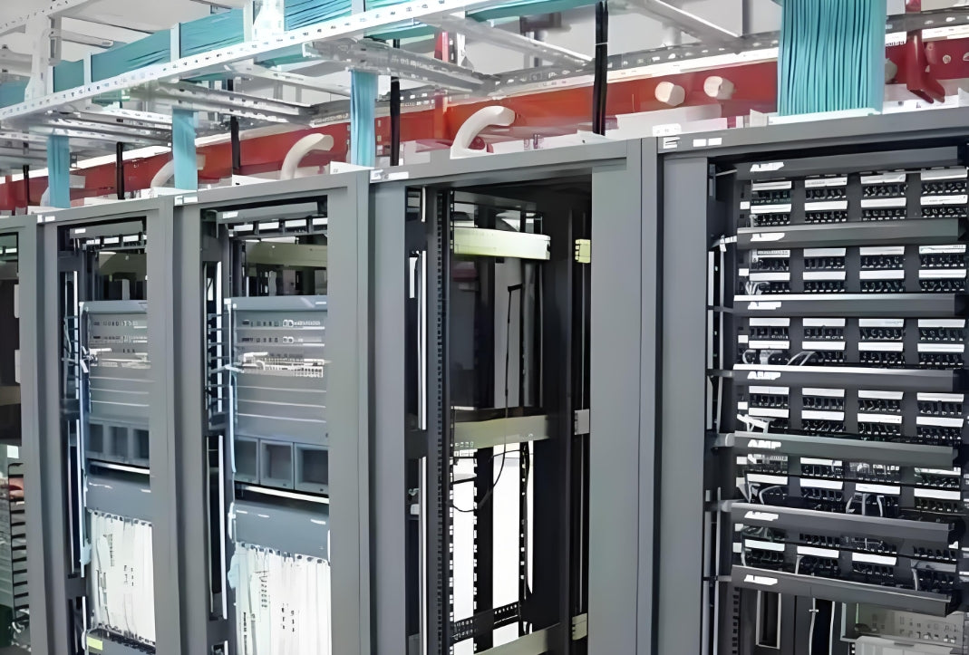
Industrial Ethernet star topology multiplies cable count per cabinet — proper cable management and planning are non-negotiable from day one of migration
Q: Does industrial Ethernet still deliver "deterministic" real-time performance?
A: Yes — but determinism now depends on network design and managed switch configuration, not on the physical layer alone. Protocols like PROFINET IRT and EtherCAT achieve sub-millisecond cycle times using time-slice scheduling in managed switches. TSN (Time-Sensitive Networking, IEEE 802.1) is the next generation of hardware-level determinism over standard Ethernet hardware. The physical cabling must support this with consistent impedance, low skew, and tight shielding — which is why cable grade selection matters as much as protocol configuration.
Chapter 3: The Five Critical Cabling Challenges in Every Fieldbus Migration
Challenge 1: Shielding and EMI in Industrial Environments
Fieldbus cables were often unshielded or used foil-only shields — adequate for the low frequencies and short distances of fieldbus. Industrial Ethernet cables at 100 MHz (Cat5e) or 500 MHz (Cat6A) are far more susceptible to electromagnetic interference from variable frequency drives (VFDs), welding equipment, and power distribution lines.
Industrial Ethernet in manufacturing environments requires S/FTP or SF/UTP shielded cable with continuous drain wire grounding at both ends. The shield must be bonded to the cabinet ground bus bar using a defined 360-degree termination method — not a pigtail ground wire, which creates an impedance discontinuity at high frequencies.
Shield Termination Best Practice
Use metallic cable glands with integrated shield termination rings where cables enter industrial enclosures. Ensure the switch chassis and end-device housing are on the same ground reference (bonded to a common equipotential bus). Inconsistent ground references cause shield current loops that corrupt signal integrity and trigger EMC failures during certification testing.
Challenge 2: Power over Ethernet (PoE) at Extended Distances and Higher Wattages
Fieldbus systems used separate power conductors — 24V DC for sensors, 24V AC for actuators — routed independently from data cables. Industrial Ethernet consolidates power and data on the same four twisted pairs, enabling PoE++ (802.3bt, up to 90W per port). This eliminates dedicated power runs to edge devices.
However, PoE in industrial environments creates compounding thermal and power delivery challenges:
- Voltage drop over 100m runs: At 90W per port, current through the cable reaches 1.875A at 48V nominal — higher gauge cables (23AWG or 22AWG) are needed to keep V-drop within acceptable limits
- Heat buildup in cable bundles: PoE power dissipation in cable jackets raises ambient temperatures; bundle size limits apply that differ from data-only installations
- Cable length vs. power budget compatibility: PoE++ requires careful cable gauge and bundle sizing analysis
Challenge 3: Bandwidth and the 400G Uplink Reality
Individual industrial Ethernet nodes may only need 1G, but the uplink aggregation from the control cabinet to the network core is where the bandwidth wall hits. A 24-port industrial managed switch at 1G per port aggregates to a 10G or 25G uplink. Multiple cabinets aggregate further to 40G/100G/400G at the data center core.
Fieldbus had no equivalent concept — bandwidth was shared on a single bus. Industrial Ethernet forces teams to plan fiber backbone capacity upfront:
Industrial Ethernet Bandwidth Hierarchy
Device level: 100M/1G copper (Cat5e/Cat6A) — per port
Cabinet aggregation: 10G/25G uplinks — Cat6A or multimode fiber (OM3/OM4)
Building/stack aggregation: 40G/100G — multimode OM4 or singlemode OS2
Data center core: 400G/800G — singlemode OS2 fiber with LC or MPO connectors
Challenge 4: Topology Migration — Managing the Hybrid Phase
Most facilities cannot execute a full fieldbus-to-Ethernet migration overnight. Hybrid topologies are the operational reality for 3–7 years. This creates three sub-challenges:
- Fieldbus gateway nodes: Protocol converters (fieldbus slave to Ethernet master) add latency and a potential single point of failure — plan redundancy
- Cable pathway congestion: New industrial Ethernet drops run alongside existing fieldbus cables in cable trays — verify tray fill ratios don't exceed TIA-569 standards
- Documentation burden: Two parallel documentation systems (old and new) must be maintained until migration completes
Challenge 5: Grounding Continuity Across the Migration
Fieldbus grounding was often inconsistent — some devices grounded, others floating. Industrial Ethernet demands continuous shield continuity from device to switch to network core. Every migration connection point is a potential grounding failure:
- Shield not terminated at patch panel
- Metal RJ45 or M12 connector housing not bonded to equipment ground
- Multiple ground references creating ground loops
- Fiber patch cords used for uplinks but copper for device drops — mixing media without proper reference planes
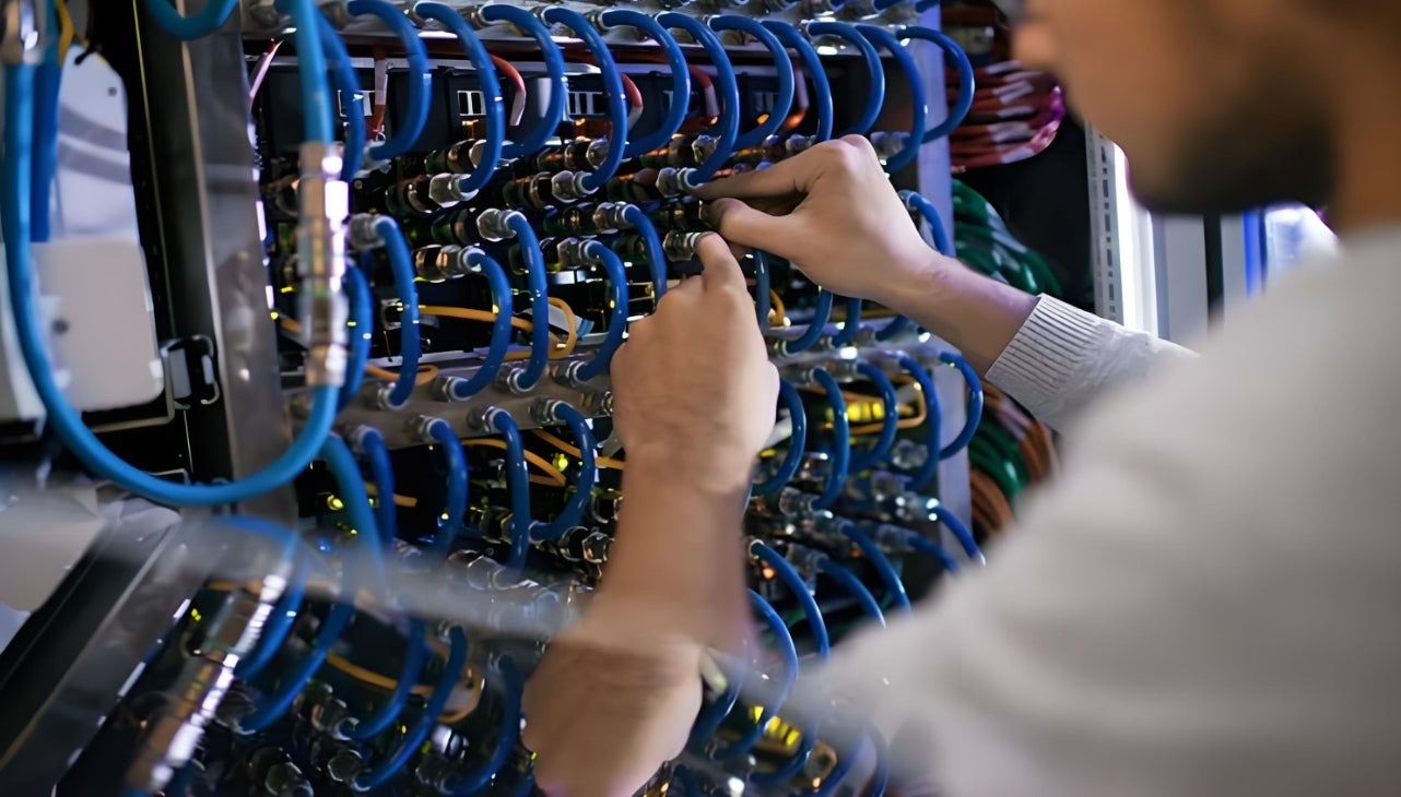
Proper industrial Ethernet cable installation — including shield bonding, strain relief, and correct bend radius — prevents the grounding and performance failures that plague most fieldbus migrations
Q: Do we need to completely redo the grounding system when migrating to industrial Ethernet?
A: Not necessarily from scratch, but you must audit and remediate. Fieldbus systems with inconsistent grounding will cause EMC failures under industrial Ethernet certification testing (EN 55032/CISPR 32). Conduct a ground continuity survey using a low-resistance ohmmeter before migration. Remediate any readings above 1 ohm between the equipment ground bus and the building ground grid. Full shield continuity verification should be part of your post-migration acceptance testing checklist.
Chapter 4: Step-by-Step Fieldbus Migration Handbook
Phase 1: Audit and Discovery (Weeks 1–4)
Migration without a complete audit of existing fieldbus infrastructure is the most common cause of budget overruns and network outages. This phase establishes the baseline.
Document the existing fieldbus network:
- Identify every fieldbus node, cable segment, connector type, and protocol variant in use
- Use a cable tracer to physically trace all fieldbus cables and verify as-built documentation
- Test shield continuity and insulation resistance on all existing cable segments
- Catalog end-device power requirements to determine PoE compatibility vs. separate power feeds
- Identify high-EMI zones (VFDs, arc welders, induction heaters) for cable routing planning
Phase 2: Network Architecture Redesign (Weeks 3–8)
Redesign the physical and logical network topology for industrial Ethernet principles:
- Define switch hierarchy: Device-level switches (unmanaged or lightly managed at the cabinet) aggregate to building-level managed switches, then to core data center switches
- Plan cable routing: Industrial Ethernet copper drops are limited to 100m maximum per segment. Map all devices within this distance of a switch location — any device beyond 100m requires fiber extension or a locally powered switch
- Select cable grades: Cat6A S/FTP shielded cable is the baseline for most new industrial Ethernet installations, supporting 10G up to 100m and full PoE++ power delivery
- Plan fiber backbone: For multi-building campus networks, OM4 multimode or OS2 singlemode backbone is mandatory for uplink speeds above 10G
- Grounding design: Design a single-point grounding architecture with equipotential bonding between all cabinets and the main ground bus
Phase 3: Procurement and Preparation (Weeks 6–12)
Key Procurement Decisions
- Industrial-grade switches: Rated for extended temperature range (-40°C to +75°C), DIN-rail mounting, redundant power inputs (24–48V DC)
- Cables: Cat6A shielded cables for horizontal drops; industrial-grade Cat6A with S/FTP construction and PVC or PUR jacket for oil/chemical exposure environments
- Connectors: M12 D-coded (100M) or X-coded (1G/10G) for harsh environments; industrial RJ45 with sealing caps for less severe locations
- Patch panels: Industrial-grade patch panels with pass-through ports for quick reconfiguration during migration; shielded versions for EMI-critical zones
Phase 4: Phased Migration Execution (Weeks 10–30+)
Execute the migration in logical functional groups — migrate one control loop or machine line at a time:
- Install new industrial Ethernet switch adjacent to the existing fieldbus master
- Deploy new Cat6A drops to each fieldbus device location; terminate at new patch panel
- Connect fieldbus devices via protocol gateway as secondary fallback path
- Test new Ethernet paths for bandwidth, latency, and packet loss before commissioning
- Commission end-devices on industrial Ethernet; verify control loop performance matches or exceeds fieldbus baseline
- Decommission old fieldbus segments after stable operation confirmed for 2–4 weeks
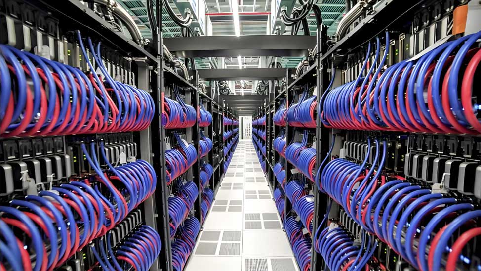
Industrial control cabinet ready for fieldbus migration — new Cat6A shielded runs terminate at a dedicated industrial patch panel, with dedicated power feeds for PoE-devices routed separately
Q: Can we run old fieldbus devices on industrial Ethernet during migration without replacing hardware?
A: In many cases, yes — using protocol gateways or fieldbus-to-Ethernet adapter modules. These devices present as an Ethernet node while driving the legacy fieldbus segment. This is a valid strategy for migrating the backbone first (industrial Ethernet to the switch level) while preserving fieldbus at the device level. However, this adds latency (~1–5 ms per gateway) and a single point of failure — always deploy gateways in redundant pairs for critical control loops.
Chapter 5: Case Study — Legacy Factory Control Network Migration
Background
A Tier-2 automotive parts manufacturer operated a 15-year-old facility with 180 Profibus DP nodes across three production lines. Control cabinets used a mix of DB9 and M12 fieldbus connectors, unshielded cable runs up to 400m, and no documented cable inventory. Annual maintenance cost for fieldbus-related failures exceeded $180,000 in downtime and replacement parts. Machine uptime KPI was 91.2%.
Challenges
- 180 fieldbus nodes across 3 buildings — no single-cutover window possible
- Critical production lines requiring 99.5%+ uptime during migration
- No existing cable tray capacity for 180 additional Cat6A drops
- EMI-rich environment: 24 VFDs and 6 resistance welders in the same building
- No as-built documentation — all cable paths had to be physically traced
Solution
- Audit phase (6 weeks): Complete cable trace and documentation of all 180 fieldbus segments; EMI zone mapping using spectrum analyzer
- Cable infrastructure (12 weeks): Installed new Cat6A S/FTP shielded runs in dedicated cable trays; 48-port industrial managed switches in each building; OM4 fiber backbone between buildings
- Migration (20 weeks, one production line at a time): Migrated non-critical auxiliary systems first (HVAC monitoring, lighting control); then migrated primary production lines during scheduled maintenance windows
- Parallel operation: Fieldbus gateway modules at each PLC maintained fallback for 4 weeks post-migration per line
Results
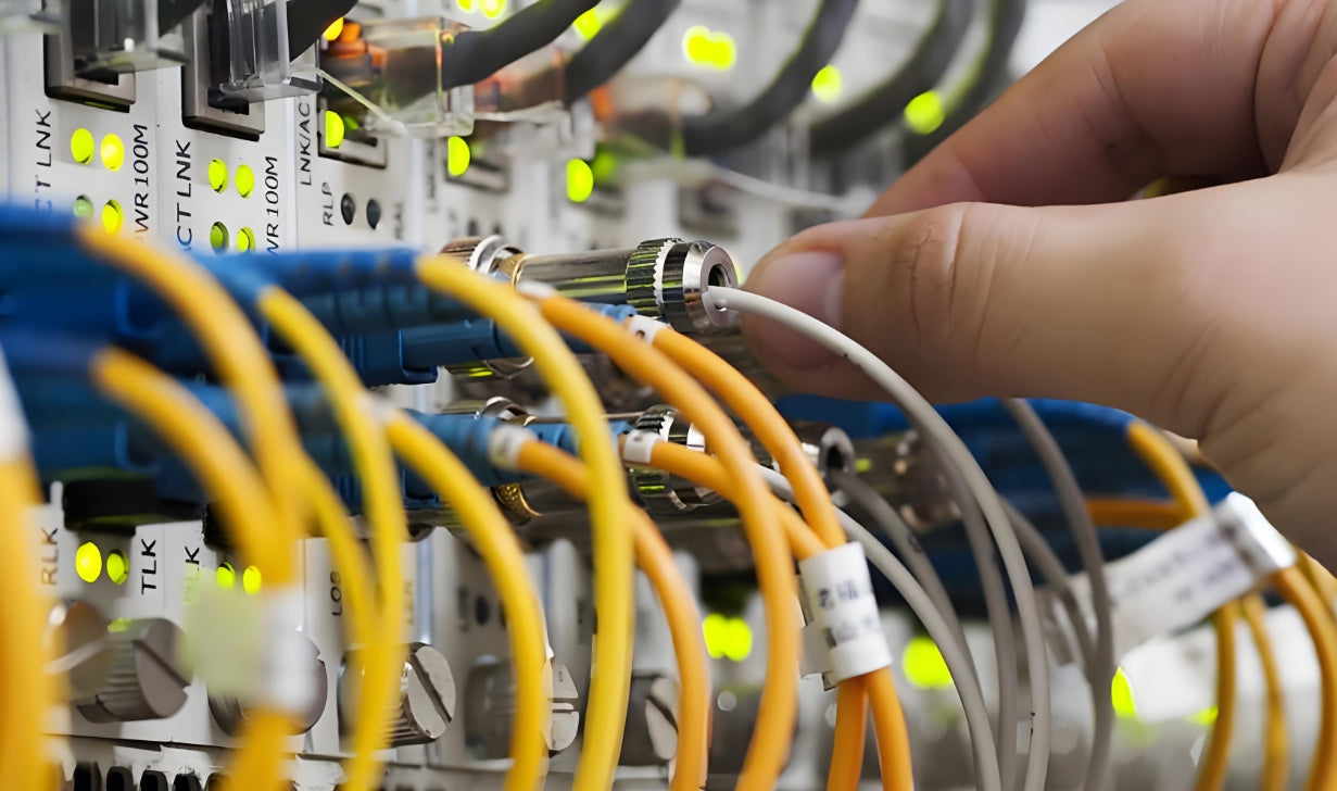
Fluke certification testing of the new Cat6A industrial Ethernet infrastructure — every link verified to TIA-568.2-D standards before commissioning
Chapter 6: Cable Selection Quick Reference — Copper Grades for Industrial Ethernet
Not all industrial Ethernet cables are equal. The right grade depends on distance, bandwidth, PoE power level, and environmental conditions. Use this reference table for procurement decisions:
| Cable Type | Max Bandwidth | Max Distance | PoE Support | Shielding | Typical Application |
|---|---|---|---|---|---|
| Cat5e U/UTP | 100 MHz | 100 m | PoE+ (71W theoretical, not recommended) | Unshielded | Low-EMI office/IT environments; not recommended for industrial use |
| Cat5e S/FTP | 100 MHz | 100 m | PoE++ (90W) with 23AWG | Overall braid + foil pair shield | Industrial light-duty; moderate EMI environments |
| Cat6 U/UTP | 250 MHz | 100 m (55m for 10GBASE-T) | PoE++ possible with 23AWG | Unshielded | Temporary installations; lab environments |
| Cat6A S/FTP | 500 MHz | 100 m (full 10GBASE-T) | Full PoE++ (90W) | Overall braid + foil pair shield | Recommended standard for all new industrial Ethernet deployments |
| Cat7 S/FTP | 600 MHz | 100 m | Full PoE++ (90W) | Dual shield ( braid + foil per pair + overall) | Heavy EMI environments; data centers; medical facilities |
| Cat8 S/FTP | 2000 MHz | 30 m (channel); 24m (permanent) | Full PoE++ | Dual shield + individually shielded pairs | Data center switch-to-switch 25G/40G aggregation; industrial for 10G backbone within cabinets |
Cable Jacket Material: PUR vs. PVC vs. LSZH
In industrial environments, cable jacket material matters as much as transmission performance. PUR (polyurethane) jackets offer excellent oil, abrasion, and UV resistance — ideal for factory floor installations. PVC jackets are cost-effective for indoor, climate-controlled environments. LSZH (Low Smoke Zero Halogen) jackets are mandatory in enclosed spaces where fire safety is critical (tunnels, ships, data centers). Always match jacket material to the installation environment — using PVC in an oil-exposed industrial zone is a common and costly mistake.
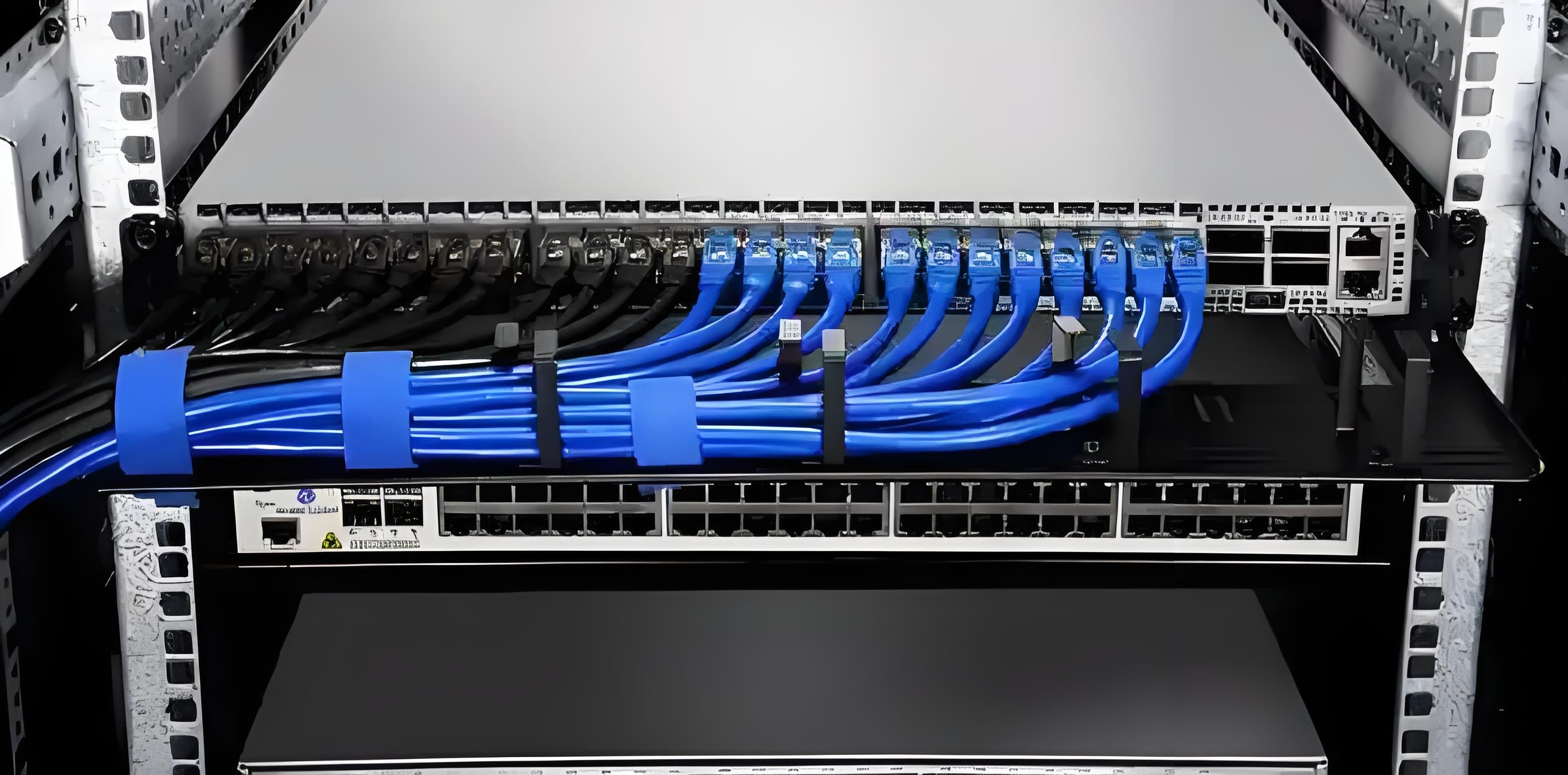
Industrial-grade Cat8 S/FTP patch cables support 25G/40G switch aggregation within control cabinets — rated for extended temperature range and continuous flexing in cable carrier applications
Q: Is Cat6A shielded sufficient for industrial Ethernet, or do we need Cat7?
A: For the vast majority of industrial Ethernet deployments, Cat6A S/FTP is the correct choice. It delivers full 10GBASE-T up to 100m, supports full PoE++ power delivery, and provides adequate EMI protection when properly terminated. Cat7 offers higher frequency (600 MHz) and superior shielding, but the installation cost premium and limited Cat7 connector ecosystem (no standard RJ45-compatible Cat7 keystone) make it unjustifiable unless you operate in extreme EMC environments or require Cat7-specific connector form factors. Reserve Cat8 for short-run, high-speed switch-to-switch links within cabinets.
Chapter 7: Future-Proofing — 400G Uplinks, SPE, and TSN on Your Horizon
The 400G Interconnect Wall
The Ethernet Alliance 2026 roadmap shows the single-lane 400G standard now in active development — a direct response to AI cluster bandwidth demands where inter-node communication bandwidth doubles approximately every 18–24 months. For industrial Ethernet infrastructure, this translates to:
- Fiber backbone must already be rated for OS2 singlemode or OM4 multimode — copper cannot support 400G at meaningful distances
- Switch ports designated for future 400G uplinks should use MPO-12 or LC duplex fiber patch panels from day one
- Plan for 800G and 1.6T transitions by ensuring fiber route diversity and sufficient spare conduit capacity
Single Pair Ethernet (SPE): The Next Node-Level Standard
SPE (IEEE 802.3cg) uses a single twisted pair to deliver 10 Mbps over 1,000m or 100 Mbps over 40m — purpose-built for industrial field-level devices: sensors, actuators, valves, and simple I/O modules that don't need gigabit speeds but require long-reach connectivity and PoDL (Power over Data Lines).
SPE: Why It Matters for Migration Planning
SPE represents the fieldbus replacement at the lowest device level — where industrial Ethernet Cat6A/Cat7 is overkill and cost-prohibitive. If your facility has hundreds of simple sensors and binary actuators on fieldbus segments, the long-term replacement path is SPE, not Cat6A. Plan your migration architecture with SPE-capable switches at the field level to avoid a second migration in 5–8 years.
Time-Sensitive Networking (TSN): Determinism Without Proprietary Hardware
TSN (IEEE 802.1) enables hardware-level determinism over standard Ethernet switches. For motion control, closed-loop automation, and safety-critical systems that currently rely on proprietary real-time fieldbuses, TSN eliminates the need for dedicated deterministic networks. This convergence means:
- One physical network for all industrial traffic (standard IT, real-time control, and media)
- Cabling infrastructure must support consistent latency, low skew, and high bandwidth across all traffic classes simultaneously
- Cat6A S/FTP is TSN-ready; Cat5e is not — another reason to standardize on Cat6A minimum
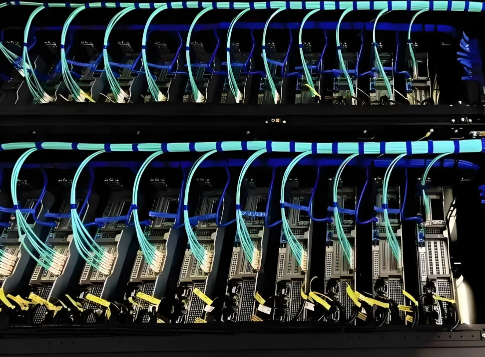
OS2 singlemode fiber backbone installation — critical infrastructure for supporting future 400G/800G uplinks and TSN traffic aggregation in next-generation industrial networks
Q: How do we build cable infrastructure today that's ready for TSN and 400G without over-specifying everything?
A: Focus on three actionable steps: (1) Standardize on Cat6A S/FTP minimum for all copper drops — this is the right baseline for the next decade. (2) Deploy OS2 singlemode fiber for all uplinks above 10G — singlemode is future-proof for 400G+ without route reinstalls. (3) Use MPO/LC fiber patch panels at all switch locations so you can reterminate for different fiber counts without recabling. This strategy covers TSN requirements, 400G, SPE aggregation, and beyond without overbuilding copper to Cat8 everywhere.
Chapter 8: Key Takeaways and Action Checklist
The migration from fieldbus to industrial Ethernet is not just a protocol upgrade — it is a fundamental redesign of your physical network infrastructure. The decisions made during this migration will determine the performance, maintainability, and future flexibility of your network for the next 15–20 years.
| # | Action Item | Priority | Timing |
|---|---|---|---|
| 1 | Complete a full fieldbus asset audit — document every node, cable, connector, and protocol variant before designing the new network | Critical | Before any procurement |
| 2 | Select Cat6A S/FTP shielded as the standard copper cable grade for all new drops — do not use Cat5e | Critical | During procurement |
| 3 | Design a single-point grounding architecture and verify ground continuity (<1Ω) across all equipment before migration begins | Critical | Pre-migration |
| 4 | Plan cable tray capacity for star topology — star topology generates 5–20x more cable runs than daisy-chained fieldbus | High | Phase 1 engineering |
| 5 | Deploy OS2 singlemode fiber for all building-to-building and core uplinks; use OM4 only for short in-cabinet runs | High | Phase 2 infrastructure |
| 6 | Use industrial-grade managed switches (DIN-rail, extended temp range, redundant DC power) for all new deployments | High | Phase 2 procurement |
| 7 | Commission all new links with Fluke certification to TIA-568.2-D standards before bringing devices online | High | Per migration batch |
| 8 | Maintain parallel operation (fieldbus + industrial Ethernet) for minimum 4 weeks per migration batch before decommissioning old segments | Medium | During migration |
| 9 | Audit and remediate any cable tray fill ratios that exceed TIA-569 limits before adding new industrial Ethernet runs | Medium | Pre-migration |
| 10 | Plan for Single Pair Ethernet (SPE) at field-level device nodes in the next 5–8 year cycle to avoid a second migration | Low (strategic) | Architecture planning |
Industrial Ethernet at 79% is not a future trend — it is the present reality. For data center and campus network teams managing this migration, the physical layer decisions made today will compound for decades. Choose Cat6A shielded, plan your fiber backbone for 400G, get the grounding right, and verify every link with Fluke certification before commissioning. These five disciplines will deliver a fieldbus migration that is reliable, maintainable, and ready for whatever comes next on the Ethernet speed roadmap.

AMPCOM Technical Team
Industry experts with 17+ years in structured cabling, industrial networking, and fiber optic infrastructure design
Need help planning your fieldbus-to-industrial Ethernet migration?
AMPCOM provides a full range of Cat6A and Cat7 S/FTP shielded cables, industrial-grade M12 connectivity, fiber optic patch panels, and cable management products engineered for industrial environments.
Talk to Our Infrastructure Experts

