MPO vs MMC: Fiber Connector Selection Guide for AI-Era Data Centers
Published:Executive Summary: As AI workloads drive data center speeds from 100G to 400G, 800G, and beyond, the choice of multi-fiber connector infrastructure has become a strategic decision — not just a procurement detail. MPO and MMC represent two fundamentally different approaches to high-density fiber connectivity. Understanding their performance trade-offs, deployment contexts, and AI-specific requirements will determine whether your network scales efficiently or becomes a bottleneck within 18 months.
Quick Navigation
- 1 The AI Data Center Connector Challenge
- 2 MPO Connectors: The Data Center Standard
- 3 MMC Connectors: Field Flexibility Meets Trade-offs
- 4 Head-to-Head: MPO vs MMC Performance Comparison
- 5 AI Workload Implications: Why Connector Choice Matters More Than Ever
- 6 Selection Framework: Choosing the Right Connector
- 7 Call to Action

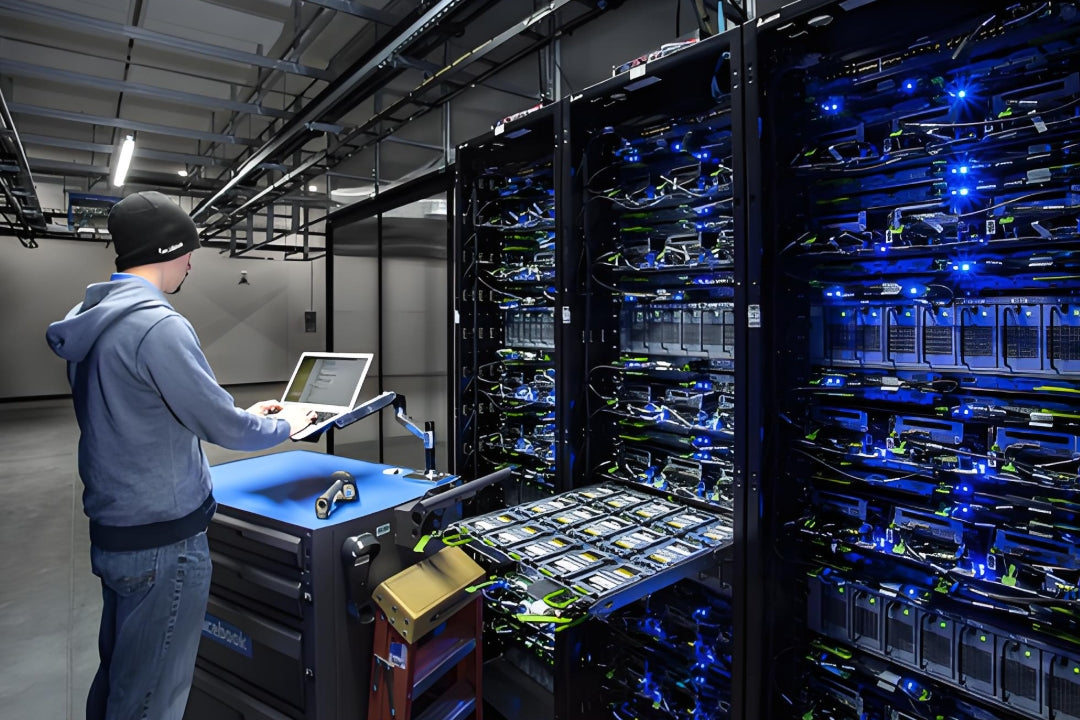
Modern AI data centers demand connector infrastructure that can support 400G, 800G, and 1.6T speeds without becoming the bottleneck
Chapter 1: The AI Data Center Connector Challenge
AI infrastructure has compressed decades of data center evolution into a handful of years. GPU clusters requiring 400G InfiniBand or 800G Ethernet uplinks, all-to-all fabric topologies, and lossless network requirements are placing unprecedented demands on the physical layer.
In this environment, the humble fiber connector is suddenly in the hot seat. A connector that added 0.5 dB of insertion loss in a 10G network might be perfectly acceptable. In an AI supercomputer running 400G SR4 transceivers over OM4 multimode fiber, that same 0.5 dB can mean the difference between a link reaching its rated distance and failing certification — or worse, passing certification at the edge of its margin and exhibiting intermittent errors during training runs.
The AI-Specific Connector Stress Factors
Dense topology: AI clusters use leaf-spine or full-mesh topologies with far more inter-switch links than traditional three-tier architectures, multiplying the number of connector mating cycles.
Vibration and thermal cycling: GPU racks generate significant heat, and AI training runs can last days or weeks. Temperature cycling stresses connector housings and ferrules, amplifying the importance of mechanical precision.
Lossless network requirements:
AI networks often require zero packet loss to avoid GPU communication timeouts. Margin-consuming connectors directly threaten this requirement.
Bandwidth density: As speeds climb from 400G to 800G to 1.6T, the per-fiber bandwidth budget shrinks, making every dB of connector loss count more than ever.
High-density computing centers require precision connector infrastructure that maintains performance under sustained thermal and mechanical stress
Chapter 2: MPO Connectors — The Data Center Standard
MPO (Multi-Fiber Push-On) connectors are the de facto standard for modern data center fiber infrastructure. Defined by IEC 61754-7 and TIA-604-5, they terminate up to 24 fibers in a single ferrule and are the foundation of 40G, 100G, 200G, 400G, and emerging 800G transceiver form factors.
Why MPO Dominates Data Centers
Speed and density: A single 12-fiber MPO connector can support 1x 100G QSFP28 link (using 4 fibers for TX/RX) or 3x 40G QSFP+ links simultaneously. As speeds increase, MPO's parallel optics approach scales elegantly.
Factory-terminated precision: MPO connectors are polished and tested at the factory, achieving insertion loss of 0.1–0.35 dB with high consistency. Each connector comes with a test report.
Key-up/key-down polarization: MPO standards define key-up and key-down variants, ensuring correct fiber mapping across the polarization universe without field errors.
MTP premium option: US Conec's MTP branded connectors (discussed in our companion Q&A article) push MPO performance further with floating ferrules and ultra-low loss ratings of 0.1 dB typical.
Common MPO Configurations
| Configuration | Fiber Count | Common Use Case | Typical Loss |
|---|---|---|---|
| MPO-8 | 8 fibers | 100G SR4 / 400G SR4.2 | 0.15–0.35 dB |
| MPO-12 | 12 fibers | 40G SR4, 100G SWDM4 | 0.15–0.35 dB |
| MPO-24 | 24 fibers | 200G SR4, 400G SR8 / SR4.2 | 0.15–0.5 dB |
| MTP-12 (US Conec) | 12 fibers | Hyperscale / AI fabric backbone | 0.10–0.35 dB |
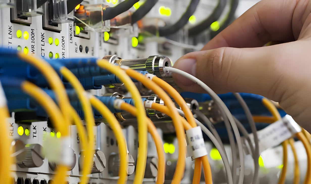
Factory-terminated MPO assemblies undergo rigorous IL/RL testing to ensure performance meets IEEE specifications for each speed grade
Chapter 3: MMC Connectors — Field Flexibility Meets Trade-offs
MMC (Multi-fiber Mechanical Connector) refers to field-installable multi-fiber splice connectors that enable on-site termination without fusion splicing equipment. Unlike MPO, which is a factory-terminated push-pull connector, MMC is designed for field deployment in FTTx, premises cabling, and situations where pre-terminated assemblies are impractical.
How MMC Works
MMC connectors use a mechanical splice mechanism: cleaved fiber ends are inserted into the connector, and a precision-aligned V-groove or split-sleeve assembly holds them in place. Some MMC designs (like the Senko MMC) use index-matching gel to reduce back-reflection at the splice point.
The appeal is clear: a field technician can terminate 12 fibers in minutes without a fusion splicer, making MMC attractive for:
• FTTx drop cable termination
• Emergency repairs in outside-plant fiber runs
• Premises cabling where exact length pre-terminations are difficult to predict
• Small deployments where buying factory-terminated assemblies is cost-prohibitive
The Trade-offs for AI Data Centers
While MMC has legitimate use cases, its performance characteristics create challenges for AI-scale data center deployments:
| Parameter | MPO / MTP | MMC (Mechanical) |
|---|---|---|
| Insertion Loss | 0.1–0.35 dB (factory) | 0.3–1.0 dB (field, variable) |
| Return Loss | >55 dB (APC) | 30–45 dB (typical) |
| Consistency | Highly consistent | Skill-dependent |
| Mating Cycles | >500 cycles | Limited / not recommended for patching |
| Terminator Type | Factory-polished PC/APC | Field-installed mechanical splice |
| Temperature Stability | Stable across wide range | Gel can degrade at extreme temps |
| Certification | Full IL/RL test report per assembly | Field OTDR or light source test |
The Key Limitation for AI Networks
MMC connectors are generally designed for single-mating, semi-permanent connections — not repeated mating cycles. In an AI data center where cables are re-patched during maintenance, expansion, and failover testing, an MMC-terminated link that gets mated 50 times may show degraded performance. MPO/MTP connectors are rated for hundreds of mating cycles while maintaining specification.
Chapter 4: Head-to-Head — MPO vs MMC Performance Comparison
For clarity, here is a direct comparison in the context of an AI data center environment:
| Criterion | MPO / MTP | MMC | Winner for AI Data Centers |
|---|---|---|---|
| Insertion Loss Budget | 0.1–0.35 dB | 0.3–1.0 dB | MPO/MTP |
| Link Budget Margin at 400G | Comfortable | Marginal to insufficient | MPO/MTP |
| Field Termination | Not recommended | Designed for field use | MMC |
| Repeatability | Excellent over 500+ cycles | Variable | MPO/MTP |
| AI/HPC Ready (400G+) | Yes — designed for it | Not recommended | MPO/MTP |
| Cost (per terminated fiber) | $$$ (factory assembly) | $ (field termination) | MMC (for small/infrequent jobs) |
| Standardization | IEC 61754-7 / TIA-604-5 | Varies by manufacturer | MPO/MTP |
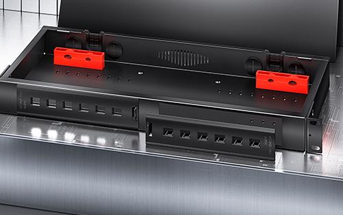
High-density fiber distribution frames in AI data centers require factory-terminated MPO assemblies for predictable, certifiable performance
Chapter 5: AI Workload Implications — Why Connector Choice Matters More Than Ever
AI training and inference workloads introduce specific physical layer requirements that amplify the importance of connector selection:
Lossless Network Requirements
RDMA over Converged Ethernet (RoCE) is the transport of choice for GPU-to-GPU communication in AI clusters. RoCE requires zero packet loss to avoid expensive retransmission that would stall GPU computation. Any connector consuming link budget margin increases the probability of congestion-induced packet drops during all-to-all collective operations.
Thermal Cycling and Long Training Runs
A large language model training run can run continuously for weeks. Over that period, rack temperatures may fluctuate, and connector ferrules expand and contract microscopically. Factory-terminated MPO/MTP connectors are designed and tested for thermal stability; field-terminated MMC connectors with index-matching gel may exhibit greater return loss drift over thermal cycles.
The 800G/1.6T Budget Crunch
At 800G and 1.6T speeds, transceiver manufacturers are already pushing the limits of optical budgets. PSM4 and SR4 form factors over OM4 multimode allow 100m and 50m reaches respectively — leaving minimal margin for connector loss. In this context, a 0.7 dB MMC connector is simply not acceptable; you need the 0.15–0.25 dB of a quality MPO/MTP assembly.
The AI Data Center Connector Rule of Thumb
For any link rated 200G or above, total connector insertion loss should not exceed 1.0 dB across all connector points in the channel. This means:
• A single MPO-to-MPO mating: ~0.15–0.35 dB — acceptable
• An MMC splice in the same channel: ~0.5–1.0 dB — risky at 200G+
• Two MMC splices + one MPO mating: potentially >1.5 dB — likely to fail
Chapter 6: Selection Framework — Choosing the Right Connector
Choose MPO/MTP When:
✓ Deploying 40G, 100G, 200G, 400G, or 800G links
✓ The data center requires Fluke/Narotam channel certification
✓ You need predictable, repeatable performance over hundreds of mating cycles
✓ You are building a structured cabling system with pre-terminated trunks
✓ AI/HPC workloads require maximum link margin and zero-loss transport
✓ You are working with QSFP-DD, OSFP, or CFP2-DCO form factors
MMC Has Its Place — But Not in the AI Core
✓ FTTx drop cable field termination (ONT, premises wiring)
✓ Emergency single-fiber repair splices
✓ Small office LAN extensions where pre-terminated assemblies are impractical
✓ Proof-of-concept or lab environments where exact fiber lengths are unknown
✗ NOT for any production link above 100G in an AI/HPC environment
AMPCOM's Recommendation for AI Data Centers
For AI-era data centers, we recommend an all-MPO/MTP architecture from day one. Specify:
• MTP-12 or MTP-24 ultra-low loss assemblies (0.1–0.15 dB typical) for trunk cables between spine/leaf switches
• MPO-12 OM4 or OM5 assemblies for server row to leaf switch connections
• Single-mode OS2 MPO-12 assemblies for any WDM or coherent 400G+ long-reach links
• Retain MMC for edge/out-of-scope fiber drops only — never in the AI compute fabric
All AMPCOM MPO and MTP assemblies come with individual IL/RL test reports. For AI deployments, we recommend requesting the detailed test data to confirm your specific assemblies fall within your optical budget calculation.
Chapter 7: Call to Action
Building an AI-ready data center requires making the right choices at every layer — and the connector is where precision matters most. AMPCOM offers a full series of MPO/MTP fiber optic high‑speed patch cords, with options for OM3, OM4, OM5 multimode and OS2 singlemode fiber.
Related Articles
- MPO Fiber Solutions for Data Center and High-Density Cabling — Choosing between 8, 12, or 24 fibers for high-density deployments
- What 800G and 1.6T Trends Mean for Data Center Cabling in 2026 — How 800G and 1.6T speeds reshape fiber infrastructure requirements
- Structured Cabling for AI Data Centers: What Is Changing — How AI is reshaping physical layer infrastructure
- How to Choose the Right Fiber Type: Singlemode vs Multimode — Matching fiber type to your AI workload requirements

AMPCOM Technical Team
Industry experts with 15+ years in enterprise network infrastructure
Building an AI-ready data center fiber infrastructure?
Contact our technical team for a free consultation and customized MPO/MTP solution for your specific AI workload requirements.
Get Free Consultation

