
AI Factory High-Density Cabling: How to Ensure Fiber Link Reliability in 100–200kW Rack Environments
Published:Executive Summary: The AI factory era has rewritten the physics of data center cabling. NVIDIA GB200 NVL72 racks draw roughly 120kW each, GB300-class systems push past 132kW, and next-generation platforms are already being designed for 200kW per rack — 15 to 25 times the power density of a traditional enterprise rack. At these densities, fiber links — not switches, not GPUs — are often the first component to fail. Tightened optical budgets, extreme heat, cramped bend radii, and contamination-prone MPO connectors combine into a reliability challenge the industry has never faced at this scale. This article breaks down the five physical-layer failure mechanisms threatening fiber links in 100–200kW environments and delivers a practical design, routing, and testing playbook for keeping AI clusters online.
Quick Navigation
- 1 The 100–200kW Reality: Why Fiber Links Fail First in AI Factories
- 2 Thermal Stress: What 100–200kW Heat Does to Optical Performance
- 3 Bend Management Under Extreme Density: Macrobend, Microbend, and MPO Physics
- 4 Connector Reliability: Contamination, Loss Drift, and MPO Cleaning Discipline
- 5 Routing for Serviceability: Pathways, Airflow, and Liquid-Cooling Integration
- 6 Testing and Certification: Proving Reliability Before GPUs Are Installed
- 7 The Bottom Line: A Fiber Reliability Checklist for AI Factory Buildouts

At 100–200kW per rack, the physical layer — not the silicon — becomes the first reliability bottleneck in AI factory infrastructure
Chapter 1: The 100–200kW Reality — Why Fiber Links Fail First in AI Factories
Power Density Is No Longer a Design Preference — It Is the Design
For two decades, the standard enterprise rack drew 7–10kW. Early AI deployments pushed that to 30–40kW, and cabling teams adapted. The current AI factory generation has left those numbers behind entirely:
Every one of those kilowatts must be fed by power cabling, and every one of those fiber strands must survive the thermal, mechanical, and spatial environment the power creates. Meanwhile, link budgets have moved in the opposite direction: where 100G links enjoyed 5–7dB of channel loss budget, an 800G-DR8 link allows only ~3dB end to end. A marginal splice, a dusty connector, or a slightly-too-tight bend that would have been invisible at 100G now pushes a link past its optical budget.
What Actually Breaks First
Field data from AI factory commissioning is remarkably consistent. The electronics — GPUs, switches, transceivers — are tested by their vendors and rarely the first failure point on a new build. The failures cluster in the physical layer:
- Connector contamination on MPO arrays (the #1 cause of intermittent link errors)
- Bend-related loss from cables crushed or over-bent during high-density installation
- Thermal drift in connector and patch cord materials under sustained high temperature
- Airflow blockage from unmanaged fiber bundles, which raises temperatures further and accelerates every other failure mode
This matches the experience documented in our deep-dive on what actually breaks first in AI data center cabling — the failure sequence is physical, predictable, and preventable if the cabling system is designed for the density from day one.
Case Study: The 40% Commissioning Failure
A hyperscale operator commissioning a 1,000-rack AI factory ran full Tier 1 + Tier 2 certification on every fiber link before GPU installation. The result: over 40% of MPO-based links initially failed the 800G insertion-loss budget. Root causes were almost evenly split between contaminated endfaces (dust accumulated during cable pull-in) and connectors mated without inspection. None of the failures were in the fiber itself. After implementing mandatory inspection-and-clean before every mate, the retest pass rate exceeded 99%.
❓ Why do fiber links fail before electronics in AI factories?
Transceivers and switches are vendor-tested components; the cabling system is assembled on site under construction conditions. At 100–200kW density, hundreds of MPO connections are made in tight, dusty, high-temperature spaces — every mate is an opportunity for contamination, misalignment, or bend damage. Tighter 800G budgets (≈3dB) mean those small physical defects now cross the failure threshold.
❓ What makes AI factory cabling different from a classic enterprise data center?
Four things: power density (15–25× higher), cooling architecture (liquid cooling changes where cables can and cannot run), fiber count per rack (500+ strands vs a few dozen), and link speed (800G/1.6T budgets are far tighter than 10–100G). A cabling design that was "good enough" in a 7kW rack becomes the critical failure point at 120kW.
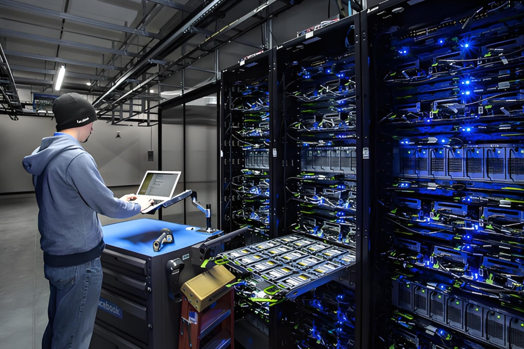
AI factory racks terminate hundreds of fibers each — every strand must be designed, routed, and certified for survival in extreme thermal environments
Chapter 2: Thermal Stress — What 100–200kW Heat Does to Optical Performance
The Temperature Map Around a 100kW+ Rack
Liquid cooling removes the bulk of GPU heat, but it does not make the rack cold. The temperature environment around a high-density AI rack is far more hostile than anything in a classic data center:
- Top-of-rack and overhead tray zones routinely see 45–55°C ambient where fiber trunks and patch cords live
- CDU and manifold zones radiate heat from hot coolant return lines
- Rear-door heat exchangers and air-cooled residual components create localized hot spots
- Transceiver cages at the switch face push heat directly into adjacent patch cord ends
How Heat Attacks the Optical Path
Heat degrades fiber links through four distinct mechanisms, each with a different time constant:
| Mechanism | What Happens | Timescale | Typical Impact |
|---|---|---|---|
| Connector ferrule expansion | Zirconia ferrule and metal housing expand at different rates, shifting core alignment | Minutes (per thermal cycle) | 0.1–0.3 dB drift per mated pair |
| Epoxy/adhesive softening in terminated ends | Potted fiber in connectors shifts under stress at sustained high temperature | Weeks–months | Gradual insertion-loss rise, eventual intermittent faults |
| Cable jacket & coating aging | Jacket softens or becomes brittle; coating stress on fiber increases attenuation | Months–years | Accelerated aging, jacket cracking near hot exhaust paths |
| Transceiver heat soak | Hot patch cord ends heat the transceiver face, raising bit-error rates near link budget limits | Continuous | Marginal links become unstable under load |
Standard silica fiber itself is remarkably heat-tolerant — attenuation shifts are small even at 100°C. The connectors, adhesives, and jackets are the weak points, which is why component selection matters more than fiber selection in hot AI zones. This is also why the choice of singlemode vs multimode fiber must be made together with operating-temperature planning: OS2 singlemode systems tolerate heat and tight budgets far better than multimode at 800G distances.
Design Rules for Thermal Reliability
- Specify high-temperature-rated patch cords (jacket rated to 75–85°C) in all rack-adjacent zones
- Keep slack loops and patch cords out of direct exhaust paths — route above or beside hot zones, never through them
- Use fiber trays and ducting to shield cables from radiant heat of manifolds and CDUs
- Plan for thermal cycling: expansion and contraction of long trunk runs will move connector endfaces; secure slack with strain relief, not tight ties
❓ What temperature do patch cords actually experience next to a 100kW rack?
Measurement campaigns in AI factories show sustained 45–55°C at the top of racks and in overhead trays, with transient spikes above 60°C near rear-door heat exchangers and CDU manifolds. Standard patch cords rated to 60–75°C still work, but their margin disappears — specifying 75–85°C-rated cords in these zones buys long-term stability.
❓ Does heat permanently damage fiber?
The glass rarely — attenuation changes are reversible and small. The permanent damage accumulates in the system around the glass: connector epoxy degrades, ferrules develop micro-cracks from repeated thermal cycling, and jackets lose flexibility. That is why "heat-damaged" links almost always test as connector or patch cord failures, not fiber failures.

Thermal management is a cabling discipline at AI scale — connectors, adhesives, and jackets fail long before the glass does
Chapter 3: Bend Management Under Extreme Density — Macrobend, Microbend, and MPO Physics
Density Forces Physics to the Limit
Five hundred fibers per rack do not fit in a rack without compromise. Cables are routed through 1U MPO cassettes, behind zero-U vertical managers, and around liquid-cooling manifolds. The result: bend radii that would have been rejected outright in a conventional data center become daily reality.
Two bend failure modes matter:
- Macrobends — large-radius bends that leak light out of the core. Loss rises sharply at 1550nm, the wavelength used by most AI-factory singlemode links. A 10mm-radius bend on standard G.652.D fiber can add 0.5–1dB of loss; the same bend on bend-optimized fiber adds a fraction of that.
- Microbends — tiny deformations from cable ties over-tightened, cables crushed under other cables, or tight wraps in patch panels. Microbends are insidious because they are invisible and often intermittent, appearing only when the cable warms up and expands.
Fiber Choice: G.657 Is No Longer Optional
In 100–200kW environments, bend-optimized singlemode fiber (ITU-T G.657.A2, also labeled B6a2) should be the default for all rack-level patch cords and jumpers. G.657.A2 maintains performance at 7.5mm bend radius — roughly half of what standard G.652.D tolerates — and it is fully backward compatible with G.652.D infrastructure. The small premium per meter buys the single biggest reliability margin available at the physical layer.
MPO Architecture: 12, 16, or 24 Fibers?
High-density AI factories converge on MPO-based trunking, but the strand count decision shapes every downstream choice:
| Factor | MPO-12 | MPO-16 | MPO-24 / VSFF (SN, CS) |
|---|---|---|---|
| Fiber count per connector | 12 | 16 | 24 / 2 (duplex VSFF) |
| 800G DR8 / SR8 support | ❌ Requires 2× MPO-12 with harness | ✅ Native single-connector | ✅ Native (or via breakout) |
| Rack density | Baseline | +33% over MPO-12 | Highest (up to 2× MPO-16 density in same faceplate) |
| Breakout flexibility | Good for 100G/400G | Standard for 800G era | Best for 1.6T planning |
| Migration risk | High (800G needs re-cabling) | Low (native 800G, path to 1.6T) | Lowest (density headroom) |
For new AI factory builds in 2026, MPO-16 should be the default trunking choice, with MPO-24 or VSFF connectors reserved for switch faces where port density demands it. Our detailed comparison of MPO fiber solutions for high-density cabling walks through the 8-, 12-, and 24-fiber trade-offs in depth.
Polarity and Bend Discipline
Bend management fails most often at three specific points: the rear of the patch panel (cables bent 90° into cassettes), the vertical cable manager (bundles crushed by their own weight), and the rack-adjacent service loop (coiled too tightly). Enforce these rules:
- 10× cable OD as the minimum bend for trunk cables, 15× preferred
- Never coil slack tighter than 30mm diameter — even G.657.A2 has limits
- Use horizontal cable managers with proper radii at every patch panel; do not rely on the cable's flexibility
- Verify polarity method (A/B/C) per TIA-568 before installation; MPO rework is expensive and bend-damaging
❓ What is the minimum bend radius for OS2 fiber inside a rack?
For G.657.A2 (bend-optimized) patch cords, the manufacturer-rated minimum is typically 7.5mm, but that is a survival limit, not an operating limit. In high-density racks, design to 10× cable OD for trunks and keep patch cord loops above 30mm diameter. Standard G.652.D fiber should never be bent below 10mm — at AI densities it will fail link budgets.
❓ MPO-16 or 2× MPO-12 for 800G?
800G-DR8/SR8 optics use 8 lanes and are natively served by a single MPO-16. The 2× MPO-12 harness approach works but doubles connection points, doubles cleaning requirements, and consumes extra rack faceplate space — the opposite of what 100–200kW density demands. New builds should standardize on MPO-16.
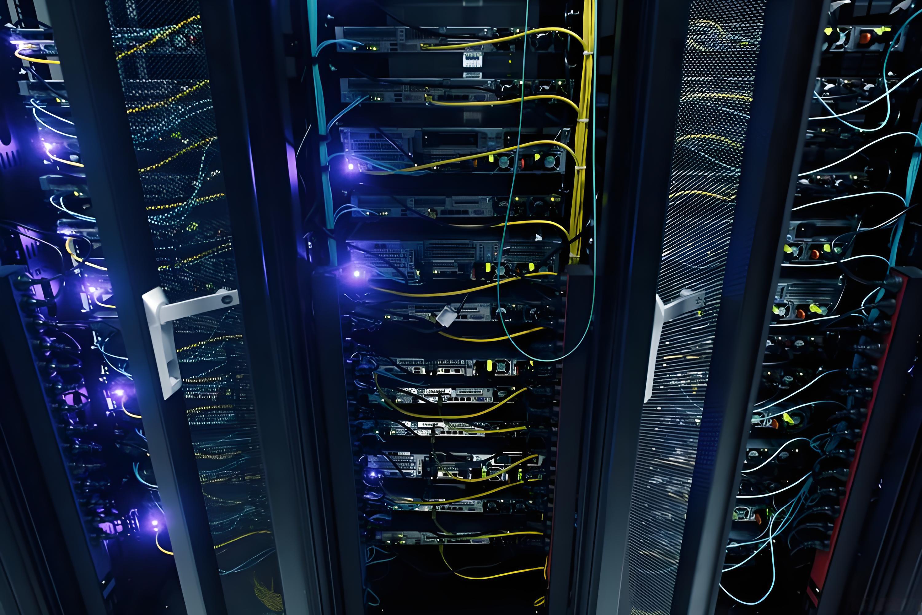
MPO-16 trunking with bend-optimized fiber is the reliability backbone of 800G AI factory cabling
Chapter 4: Connector Reliability — Contamination, Loss Drift, and MPO Cleaning Discipline
Contamination: The #1 Field Failure Cause
In the AI factory, connector contamination is not a maintenance nuisance — it is a link reliability crisis. Consider the geometry: a singlemode fiber core is 9µm across. A dust particle just 1µm in size — invisible to the naked eye — can partially block the core and add 0.5–2dB of loss. On an 800G link with a ~3dB total budget, one particle can consume two-thirds of the entire optical allowance. On MPO-16 connectors, the contamination risk multiplies by 16 fibers per connector face.
Case Study: The Intermittent CRC Mystery
An AI cluster suffered intermittent CRC errors on a single GPU-to-switch link for three weeks. Transceivers were replaced twice; the switch port was declared healthy; the link "passed" a quick light-source check. The fault finally traced to a single contaminated fiber in an MPO-16 connector — a 2µm particle that shifted position as the rack warmed up, causing loss to oscillate between 0.3dB and 2.1dB. One inspection scope session found and fixed what three weeks of electronics-level troubleshooting missed.
The Cost of a Single Bad Mate
Contamination damage is not always cleanable. Particles ground between mated endfaces can create permanent pits and scratches (the "core damage" pattern visible under a 400× scope). Once a connector endface is damaged, the entire cable or cassette must be replaced — at 100–200kW density, in a live AI factory, that is a multi-hour outage in a revenue-critical environment.
Cleaning and Inspection Discipline That Scales
Best practice for AI-factory MPO environments is uncompromising:
- Inspect before every mate — use a 400× scope with MPO adapter, per IEC 61300-3-35 criteria
- Clean, then inspect, then mate — wet-to-dry cleaning (lint-free wipes + optical-grade solvent) for heavy contamination, dry cleaning for routine touch-ups
- Cap everything, always — every unplugged connector gets a dust cap; dangling uncapped MPOs are contamination events waiting to happen
- Never touch endfaces — ferrule faces are handled only with tools, never fingers
- Track reconnection cycles — MPO connectors have a rated mating life (typically 500 cycles); AI factory moves/adds/changes burn cycles fast
The manageability constraints of 800G-era fiber designs — where every connection point counts against a shrinking budget — are covered in our analysis of how 800G changes which fiber designs remain manageable.
❓ How often should MPO connectors be cleaned?
Not on a schedule — on a process. Every unmated connector should be inspected before every mate, and cleaned if inspection fails. In high-vibration or high-temperature zones, schedule proactive inspection of critical uplinks every 6–12 months. "Clean once at install" is the leading cause of contaminated-link failures in year two.
❓ What insertion loss is acceptable for an 800G MPO link?
Budget end to end for 800G-DR8 is ≈3dB total channel loss. A healthy short AI-factory link typically measures 1.0–1.5dB (cassette + trunk + two mated pairs + breakouts). Per mated pair, plan for ≤0.3dB (LC) and ≤0.35dB (MPO). If your Tier 1 test shows more than ~1.5dB on a short link, investigate before commissioning — it will only get worse with temperature.
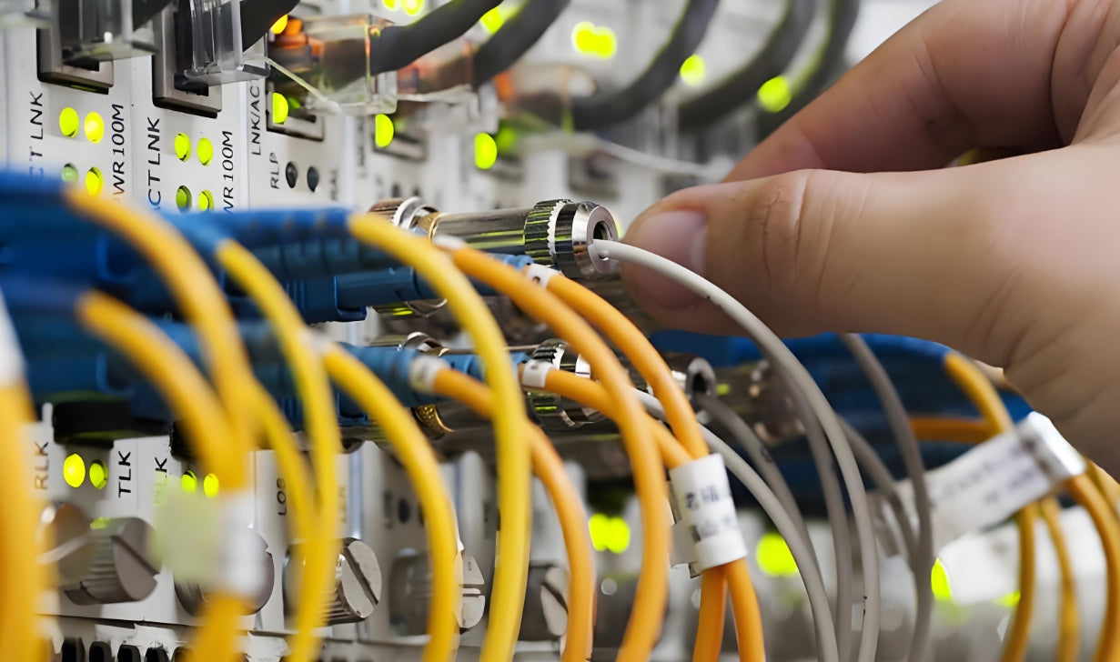
Inspection before every mate is the cheapest reliability insurance available — one 1µm particle can consume two-thirds of an 800G link budget
Chapter 5: Routing for Serviceability — Pathways, Airflow, and Liquid-Cooling Integration
Liquid Cooling Changes the Routing Rules
At 100–200kW, liquid cooling is mandatory: cold plates on GPUs, rear-door heat exchangers, row-level CDUs, and overhead coolant manifolds. This creates a new physical environment for cabling:
- Overhead space is contested — coolant manifolds and fiber trays now share the same ceiling zone
- Leak risk zones exist — cabling should avoid running directly beneath manifold connections and quick disconnects
- Service access matters more — when a GPU tray is swapped, fiber runs must move out of the way without being unplugged
Pathway Architecture That Keeps Links Reliable
The most reliable AI-factory layouts follow a strict separation discipline:
| Pathway | Recommended Use | Reliability Rationale |
|---|---|---|
| Overhead fiber trays (above coolant level) | Trunk cables, backbone, long horizontal runs | Keeps fiber away from leak paths and hot exhaust; preserves service access |
| Rack-level vertical managers | Patch cords to switch faces, short jumpers | Controlled bend radii; keeps fiber off the floor and out of airflow |
| Underfloor or separate power paths | Power cabling, coolant distribution where possible | Maintains 3–6 inch separation from fiber; prevents EMI and physical crushing |
| Service loops at both ends | Every trunk and every rack drop | Enables moves/adds/changes without re-termination — the #1 serviceability requirement |
Airflow is the hidden link between routing and reliability. Every unmanaged fiber bundle blocking a cold-aisle path raises inlet temperatures, which raises transceiver temperatures, which pushes marginal links over the edge. Well-planned data center layout and cable management is therefore not aesthetics — it is thermal engineering.
Labeling and Documentation: The Day-2 Survival Kit
In a 500-fiber rack, unlabeled fiber is unmanageable fiber. Follow TIA-606-style labeling end to end — rack, panel, port, and cable identifiers — and keep as-built documentation synchronized with every move. AI factories are re-cabled continuously as GPU generations churn; the teams that survive are the ones whose documentation survives.
Case Study: Design for GPU Churn
One operator planned its AI factory around a "GPU swap in under 2 hours" SLA. The cabling design made this possible: every rack drop terminates in a labeled service loop above the rack, every trunk has 5m of slack coiled on a tray, and all patch cords are length-planned so they reach any switch port without rerouting. When the operator migrated from 400G to 800G leaf switches, the fiber plant was untouched — only the patch cords and cassettes changed.
❓ Should fiber run above or below a liquid-cooled rack?
Above — in dedicated trays positioned above or beside coolant manifolds, never directly beneath quick-disconnect points. Fiber below the rack competes with power and coolant routing, is exposed to floor-level contamination, and complicates GPU tray service. Overhead fiber trays with controlled bend radii are the industry standard for AI factories.
❓ How much slack should you leave in an AI rack?
At minimum, one full service loop (1–2m coiled at 30mm+ diameter) at both ends of every trunk, and patch cords sized so they reach any port in the rack without stretching. Slack is not waste — it is the difference between a 10-minute re-patch and a 3-hour re-termination when the next GPU generation arrives.
Disciplined pathway separation — fiber above, power below, service loops everywhere — keeps 500-fiber racks serviceable and reliable
Chapter 6: Testing and Certification — Proving Reliability Before GPUs Are Installed
Why AI Factories Need a Different Testing Standard
Traditional data center practice tests a sample of links at commissioning and trusts the rest. At 100–200kW density with 3dB budgets, sampling is gambling. The AI factory standard is simple: test every fiber, before GPUs arrive, and again after every significant change.
Tier 1 + Tier 2: Both, Every Time
| Test | What It Measures | Why It Matters at AI Density |
|---|---|---|
| Tier 1 — OLTS (light source + power meter) | End-to-end insertion loss and polarity | The go/no-go gate against the 800G channel budget |
| Tier 2 — OTDR | Locates loss events: bad splices, crushed cables, tight bends | Turns "link failed" into "fix this connector at this distance" |
| Endface inspection | Contamination and physical damage per IEC 61300-3-35 | Catches the #1 failure cause before it becomes an outage |
Realistic Pass Thresholds for Short AI Links
Keep every test report: Tier 1 results per fiber, OTDR traces, and inspection records. These documents are the evidence trail when a link fails in year two — and the procurement-grade proof that the cabling, not the optics, is healthy. If your team is new to reading certification output, our guide to reading Fluke test reports covers what matters and what to ignore.
Testing Discipline Through the Link's Life
- At commissioning: 100% Tier 1 + Tier 2 + endface inspection on every fiber
- After every move/add/change: Tier 1 on the affected links, inspection on every connector touched
- After thermal events: any link that ran above its rated temperature gets re-verified
- Periodically: spot-check OTDR traces on long trunks to catch developing bends or crushed sections
❓ Tier 1 or Tier 2 — do we really need both?
Yes, at AI density. Tier 1 tells you a link fails; Tier 2 tells you where and why. Without Tier 2, a failed 800G link means manually probing every connector and splice along the path — hours of downtime in a 500-fiber rack. With both, the fix is usually located in minutes.
❓ Do you need to test every fiber in an MPO trunk?
Every fiber that carries traffic — which at 800G means all 8 lanes of every MPO-16 connector, and all 16 fibers if the trunk is fully used. MPO testers with reference-grade MPO patch cords make full-strand testing fast; skipping fibers to save time is how "we tested it" becomes a 2AM outage.
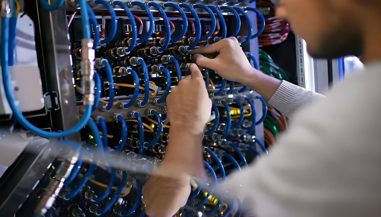
Full certification before GPU installation — Tier 1, Tier 2, and endface inspection on every fiber — is the only standard that matches 800G budgets
Chapter 7: The Bottom Line — A Fiber Reliability Checklist for AI Factory Buildouts
Fiber link reliability in 100–200kW environments is not achieved by luck or by heroic troubleshooting. It is engineered in four phases — design, install, certify, and operate. Here is the checklist that covers every decision point:
| Phase | Non-Negotiable Requirements |
|---|---|
| Design | Bend-optimized G.657.A2 fiber for all rack-level cabling; MPO-16 trunking for 800G; high-temperature-rated patch cords in hot zones; overhead fiber trays above coolant level; labeled service loops at both ends |
| Install | 10× OD minimum bend for trunks; never coil slack below 30mm; separate fiber from power (3–6 in); never route fiber beneath manifold connections; cap every connector the moment it is unplugged |
| Certify | 100% Tier 1 + Tier 2 + endface inspection before GPU install; document everything (TIA-606 labels, test reports, OTDR traces); investigate any link above 1.5dB before commissioning |
| Operate | Inspect before every mate; proactive re-inspection every 6–12 months in hot/vibration zones; re-certify after every move/add/change; track MPO mating cycles |
🎯 What is the single most important investment for fiber reliability at 100–200kW?
Cleaning and inspection discipline — combined with full certification. Contamination causes more AI-factory link failures than every other physical-layer cause combined, and it is entirely preventable. An inspection scope and a cleaning kit cost less than one hour of GPU cluster downtime.
🚀 Where should a team upgrading to AI density start?
Re-baseline the fiber plant: certify every existing link, verify bend radii and thermal exposure of all rack-level cabling, and replace standard patch cords with G.657.A2 high-temperature-rated ones in hot zones. Then standardize MPO-16 for all new 800G trunking. The checklist above is designed to be executed in exactly that order.

AMPCOM Technical Team
Industry experts with 17+ years in structured cabling, data center infrastructure, and fiber optic network design
Building an AI factory? Your fiber plant can't afford a second chance.
AMPCOM provides high-density fiber solutions for 100–200kW environments — MPO-16 trunking, G.657.A2 patch cords, high-temperature-rated cabling, and cable management products engineered for AI-scale reliability.
Talk to Our Infrastructure Experts

