10 Costly Fiber Optic Cable Installation Mistakes to Avoid in 2026
Published: Updated:Executive Summary: Fiber optic cable failures cost enterprises an average of $15,000 per hour in network downtime—yet most catastrophic losses stem from a handful of preventable installation errors. From MPO fiber deployments in hyperscale data centers to single-mode links in industrial environments, this guide dissects the 10 most expensive fiber optic cable installation mistakes that infrastructure managers encounter—and provides actionable solutions to avoid them.
Quick Navigation
- 1 Ignoring Minimum Bend Radius Requirements
- 2 Exceeding Pulling Tension Limits
- 3 Neglecting Connector End-Face Inspection and Cleaning
- 4 Mixing Singlemode and Multimode Fiber Types
- 5 Improper Cable Routing and Pathway Selection
- 6 Using Copper Cable Tools for Fiber Work
- 7 Skipping Testing, Certification, and Documentation
- 8 Failing to Protect Against Moisture and Environmental Hazards
- 9 Poor Labeling and Cable Management Practices
- 10 Rushing Fusion Splicing Without Proper Preparation
- Q&A Key Questions Answered

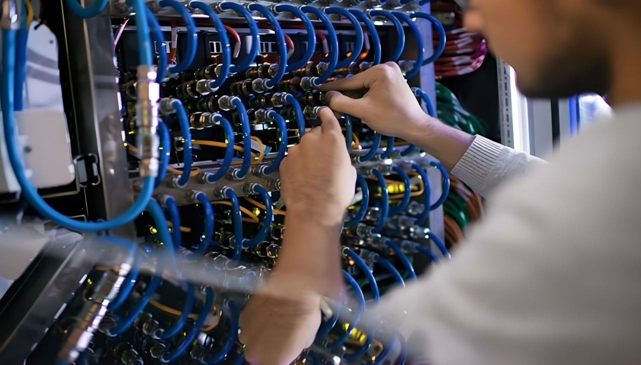
Professional fiber optic installation requires meticulous attention to detail across every phase of deployment
1. Ignoring Minimum Bend Radius Requirements
The single most common cause of chronic signal degradation in enterprise fiber networks is bend radius violations. Optical fiber is fundamentally glass—remarkably strong under tension but brittle under compression and shear. When fiber bends beyond its rated minimum bend radius, light leaks through the cladding rather than bouncing along the core, resulting in attenuation that degrades network performance silently and progressively.
Bend radius specifications vary by fiber type and installation context:
| Fiber Type | Installation (Dynamic) Bend Radius | Loaded (Static) Bend Radius | Common Application |
|---|---|---|---|
| OM3/OM4 Multimode | 7.5× cable diameter | 10× cable diameter | Data center horizontal runs |
| OM5 Wideband Multimode | 7.5× cable diameter | 10× cable diameter | Short-wave division multiplexing |
| OS2 Single-Mode (G.652.D) | 10× cable diameter | 15× cable diameter | Long-haul and campus backbone |
| Bend-Insensitive Single-Mode (G.657.A1) | 10× cable diameter | 10× cable diameter | FTTH and tight conduit routing |
| Bend-Insensitive Single-Mode (G.657.A2) | 5× cable diameter | 7.5× cable diameter | Space-constrained installations |
The distinction between static and dynamic bend radius is critical. Static bends occur when cables are permanently installed in trays or conduits—these can be slightly tighter because there is no movement. Dynamic bends occur during installation when cable is being pulled through pathways; the mechanical stress requires greater margin.
Real-World Consequence
A 2024 case study from a Tier-2 colocation facility documented a recurring 2.8 dB loss on a 100-meter OM4 link that passed initial testing but degraded over six months. Investigation revealed the installation contractor had routed fiber around a 90-degree corner with only 15mm radius on a 3mmjacketed cable—well below the 30mm minimum. The fix required recabling the entire run at a cost of $12,000 in materials and labor, plus 18 hours of network downtime.
Prevention strategy: Specify G.657 bend-insensitive fiber for any installation with tight routing constraints. Mandate sweeping bends (minimum 6× the tightest available radius) in conduit specifications. Train installation crews to use bend radius guides during placement.
2. Exceeding Pulling Tension Limits
Fiber optic cables are not designed to withstand the same pulling forces acceptable for copper twisted-pair. The aramid yarn strength members (Kevlar or similar) can absorb considerable tensile load, but the glass fiber inside has an elongation limit of less than 1%. Exceed that threshold, and microscopic fractures propagate through the core—initially invisible to OTDR testing but progressively degrading signal quality over months of operation.
Maximum pulling tension varies significantly by cable construction:
| Cable Construction | Maximum Pulling Tension (Installation) | Maximum Pulling Tension (Loaded) | Pulling Method |
|---|---|---|---|
| Premise/Indoor Tight-Buffer | 200–600 lbf (890–2,670 N) | 100–300 lbf (445–1,335 N) | Pull sock on strength member |
| Interlocking Armor Indoor/Outdoor | 600–1,000 lbf (2,670–4,448 N) | 300–600 lbf (1,335–2,670 N) | Pulling grip over armor |
| Gel-Filled Loose Tube Outdoor | 600–2,700 lbf (2,670–12,015 N) | 200–600 lbf (890–2,670 N) | Pulling eye on central strength member |
| Blown Fiber / MicroCore | Not pulled—air blown | N/A | Pneumatic installation |
A common mistake is pulling pre-terminated cables by the connector or the jacket. The connector housing is not bonded to the strength member—pulling it simply pulls the connector off the cable. The corrugated armor on armored cable is also not the pulling point; the internal central strength member is the only appropriate attachment.
Proper Pulling Technique
1. Identify the strength member: For tight-buffered cables, this is the aramid yarn bundling at the jacket. For loose-tube cables, this is the central fiberglass rod. Never pull by the outer jacket or armor.
2. Use appropriate hardware: Pull socks for tight-buffer cables; factory-installed pulling eyes or swivel clevis grips for loose-tube cables. Always use a swivel connector between the pull rope and cable.
3. Monitor tension continuously: Use a tension meter on long runs. Stop immediately if tension spikes above rated limits.
4. Apply cable lubricant: For conduit pulls exceeding 50 meters or containing multiple bends, use fiber-safe lubricant to reduce friction by up to 60%.
5. Support intermediate access points: On multi-story buildings, use manholes or pull boxes at every third floor to分段 tension.
3. Neglecting Connector End-Face Inspection and Cleaning
If bend radius violations cause the most insidious, slowly-developing failures, connector contamination causes the most immediate and catastrophic ones. Research consistently shows that 85% of fiber optic network failures trace back to dirty or damaged connector end faces. The problem is invisible to the naked eye—dust particles, oil from skin contact, and residue from cleaning materials all create scattering and absorption that dramatically increases insertion loss and return loss.
Dust particles on a fiber end face behave like boulders in a river. At the microscopic scale, a 1-micron dust particle on a 9-micron single-mode core obstructs roughly 12% of the light-carrying area. More critically, particles generate heat when high-power lasers strike them, potentially pitting or cracking the physical contact (PC) polished surface.

Professional fiber inspection scopes reveal contamination invisible to the naked eye
Inspection and Cleaning Protocol (IEC 61300-3-35)
Step 1: Inspect before any connection or cleaning. Use a digital inspection scope with ≥200× magnification for single-mode, ≥400× for multimode. Capture and save images for documentation.
Step 2: Evaluate against IEC pass/fail criteria. The standard defines zones on the ferrule end face:
- Core zone (center): Zero scratches or pits allowed
- Cladding zone: Minor scratches acceptable, no pits
- Epoxy ring and contact zones: Some defects acceptable depending on connector type
Step 3: Clean only if contamination is confirmed. Dry cleaning with lint-free wipes (for loose debris) or wet cleaning with ≥99% isopropyl alcohol and lint-free wipes (for oils). Never reuse cleaning materials.
Step 4: Re-inspect after cleaning. Verify the end face passes IEC criteria before making the connection.
Step 5: Protect immediately. Install dust caps on all idle connectors and fiber adapters. Never leave an unmated connector exposed.
4. Mixing Singlemode and Multimode Fiber Types
Single-mode and multimode fiber have fundamentally different core diameters, numerical apertures, and modal characteristics. A multimode transceiver transmitting 850nm light into a single-mode fiber will experience 20+ dB of loss—effectively no light reaching the far end. This is not a marginal performance issue; it is a complete link failure.
The confusion typically arises in mixed-mode environments where legacy multimode backbone runs coexist with new single-mode expansions, or where patch cords of the wrong type are accidentally deployed in high-density patch panels.
| Fiber Specification | Singlemode (OS2) | Multimode (OM3/OM4) | Multimode (OM5) |
|---|---|---|---|
| Core Diameter | 8–10 μm | 50 μm | 50 μm |
| Cladding Diameter | 125 μm | 125 μm | 125 μm |
| Operating Wavelength | 1310nm / 1550nm | 850nm / 1300nm | 850–950nm (SWDM) |
| Typical Bandwidth | >18,000 MHz·km | 2000/4700 MHz·km | 3500 MHz·km |
| Max Distance (Ethernet) | Up to 160km (40km typical) | 400m (OM4 @ 10G) | 400m (SWDM4 @ 100G) |
| Connector Color | Blue (PC/APC) | Aqua (OM3/OM4) | Lime Green (OM5) |
Enterprise Network Scenario
A healthcare system upgrading from 1G to 10G Ethernet discovered three campus backbone links had failed post-upgrade. Investigation revealed the original 2008 installation had mixed OS1 single-mode in the main backbone conduit with OM1 legacy multimode in lateral runs. The single-mode transceivers could not function over the 62.5μm core fiber, and the legacy cables did not support the laser launch bandwidth required for 10G. Full recabling was required—$180,000 project that could have been avoided with proper fiber type documentation.
5. Improper Cable Routing and Pathway Selection
Cable routing determines the long-term survivability of fiber infrastructure. Poor routing decisions expose cables to crushing loads, thermal extremes, moisture ingress, electromagnetic interference (EMI), and physical damage from construction activities. Unlike copper cable failures that often announce themselves with immediate connectivity loss, fiber routing problems manifest gradually through increased attenuation and intermittent errors.
Common Routing Mistakes
Shared pathway with heavy copper: Copper twisted-pair cables are significantly heavier than fiber and generate localized pressure points at cable ties and support hardware. Never bundle fiber directly above copper. Use dedicated fiber trays or innerduct.
Routing near heat sources: Fiber cable jackets have temperature ratings (typically -40°C to +70°C for standard OFNP-rated cables). Routing near boiler pipes, HVAC ducts, or unshielded power conductors creates thermal cycling that degrades gel-filled buffer tubes and jacket materials.
Exposing fiber to construction areas: In mixed renovation environments, fiber cables installed in walls or ceilings during Phase 1 are frequently damaged by trades working in adjacent areas during later phases. Mark and protect all accessible fiber runs.
Best Practices for Cable Routing
Dedicated pathways: Specify separate cable trays for fiber and copper. Where fiber must share a pathway, install innerduct (smooth-walled polyethylene tubing) to provide continuous, non-compressive support.
Maintain separation from electrical: Minimum 6 inches (15cm) from power cables up to 480V; increase to 12 inches (30cm) for higher voltages or high-current conductors.
Use proper support spacing: Horizontal runs: support every 4–6 feet (1.2–1.8m). Vertical runs: support every floor or every 8–10 feet (2.4–3m), anchored at the top and bottom of each floor.
Plan for future access: Install pulling eyes or pull boxes at every junction, every 90-degree bend, and at intervals no greater than 50 meters on long runs.
6. Using Copper Cable Tools for Fiber Work
Fiber optic installation requires specialized tools that are fundamentally different from copper cable equipment. The precision demanded by glass fiber—micrometer-level cleave angles, nanometer-level surface finish, and sub-dB loss budgets—means copper tools are not just inadequate; they actively damage fiber infrastructure.
| Copper Tool | Fiber Equivalent | Why the Difference Matters |
|---|---|---|
| RJ-45 crimper | No equivalent—pre-terminated fiber uses mechanical or heat-cured adhesive systems | Fiber connectors require precise ferrule alignment and polished end faces |
| Punch-down block | Fusion splicer or mechanical splice holder | Fusion splices achieve 0.05–0.10 dB loss; punch-down concepts do not apply |
| UTP cable stripper | Precision fiber strippers with adjustable V-groove for 250μm, 900μm, 3mm coatings | Fiber coatings are 10× thinner than Cat5e jackets; wrong strip depth nicks or breaks the glass |
| Wire map tester | Optical power meter, light source, and OTDR | Copper tests continuity; fiber requires measuring loss in dB at specific wavelengths |
| RJ-45 continuity tester | Visual fault locator (VFL) or inspection microscope | Fiber continuity requires seeing light through the glass core |
Beyond the tools themselves, copper cable training does not teach the critical skills fiber work demands: handling glass shards safely, understanding mode filling vs. overfilled launch conditions, interpreting OTDR traces, and recognizing the visual indicators of end-face damage.
The Cost of Tool Mismatches
An IT manager at a regional bank recalled a case where an experienced copper technician attempted to terminate fiber patch panels using the same wire strippers and crimpers from his copper toolkit. The result: 48 LC connectors that all failed end-face inspection, $8,000 in replacement costs, and two weeks of network degradation while the vendor re-terminated the entire run with proper equipment. "He was one of our best copper guys," the manager noted. "But fiber is an entirely different discipline."
7. Skipping Testing, Certification, and Documentation
The most common post-installation failure pattern is not a dramatic cable cut or connector break—it's an undetected marginal installation that degrades over time, creating intermittent connectivity problems that consume disproportionate engineering time during troubleshooting.
Every fiber link must be tested at commissioning and documented for baseline comparison. Without this baseline, there is no way to distinguish a new installation problem from an environmental change, equipment aging, or previous undocumented modifications.
Required Tests for Every Fiber Installation
| Test Type | Equipment Required | What It Measures | Pass Criterion (Typical) |
|---|---|---|---|
| Insertion Loss (OLTS) | Light source + Power meter | Total link loss in dB | ≤ link loss budget (typically 1.0–3.5 dB) |
| OTDR Trace | Optical Time Domain Reflectometer | Event locations, splice loss, connector loss, span length | Events ≤ 0.15 dB; span within calculated budget |
| Return Loss / Reflectance | Optical Return Loss meter | Back-reflection from connectors and splices | ≥ 45 dB (UPC), ≥ 55 dB (APC) |
| Polarity Verification | Visual Fault Locator or power meter | Tx→Rx continuity on duplex links | Correct A→B polarity on both fibers |
| Bandwidth Testing (MM only) | Modal bandwidth meter or DMD test equipment | Effective modal bandwidth for laser-based systems | ≥ rated bandwidth (e.g., ≥ 4700 MHz·km for OM4) |
Documentation Requirements
Test results are only valuable if they can be retrieved and compared. Every test report must include:
Link identification: Cable ID, origin and destination locations, port references on both ends
Test configuration: Reference method (1-cord, 2-cord, or 3-cord), test wavelength (850nm/1300nm for MM, 1310nm/1550nm for SM), and reference launch conditions
Raw measurement data: Actual dB readings for each wavelength, not just pass/fail indicators
OTDR trace files: Store .sor files in a project management system linked to cable IDs—these enable remote analysis without re-testing
As-built documentation: Updated cable routing diagrams, port mapping tables, and splice/termination records reflecting actual installation
8. Failing to Protect Against Moisture and Environmental Hazards
Outdoor and industrial fiber installations face environmental challenges that indoor data center environments do not: moisture, chemical exposure, temperature extremes, UV radiation, and physical abrasion. Each of these factors degrades fiber performance on a timeline measured in months or years rather than immediately—but the cumulative effect is catastrophic cable failure without proper protection.
Outdoor fiber installations require comprehensive environmental protection strategies
Moisture is particularly insidious. Water molecules migrate through cable jackets and buffer tubes via diffusion—a process invisible during installation but progressive over 5–10 years. Once inside, water causes hydrogen darkening (signal absorption), corrosion of glass surfaces, and ice lens formation at freeze-thaw cycles that fracture fibers.
Environmental Protection Strategies
Cable Selection for Harsh Environments
Outdoor/Underground: Gel-filled loose tube cables with water-blocking yarns and corrugated steel armor. Fosters long-term moisture resistance and mechanical protection against rodent damage.
Industrial/Factory: Zero-halogen, flame-retardant armored cables (LSZH or OFCR) rated for oil, chemical, and UV exposure. Metallic armor provides EMI shielding in electrically noisy environments.
Aerial/Lashed: Figure-8 self-supporting cables with integral steel messenger wire, UV-resistant polyethylene jackets. Anti-rotational design prevents wind-induced cable twist failure.
Oceanfront/Marine: Stainless steel corrugated armor with hermetically sealed tight-buffer fibers. Tested per IEEE 802.3 for salt spray exposure minimum 1,000 hours.
Enclosure and splice protection: Every outdoor splice point and connectorized termination requires an IP67-rated or better enclosure sealed against water ingress. These enclosures must be periodically inspected—the silicone gaskets degrade over time, and rodent damage to cable entry ports is common in buried installations.
9. Poor Labeling and Cable Management Practices
Labeling is the operational backbone of any scalable fiber infrastructure. Without consistent, legible, and durable labels, moves, adds, and changes (MACs) become archaeological expeditions—tracing cables through overhead pathways, cross-referencing spreadsheets from whoever last touched the system, and ultimately cutting the wrong cable because the labeling was ambiguous.
In high-density environments (think 144-fiber patch panels or 12-fiber MPO trunks), the difference between good and poor labeling is the difference between a 15-minute patch cable swap and a 3-hour troubleshooting nightmare that impacts multiple production VLANs.
Enterprise Labeling Standards
Label durability: Use laser-printable or thermal-transfer labels rated for the environment. Indoor plenum: flame-retardant labels. Outdoor: UV-resistant polyester or vinyl labels. Cable-mounted labels should use flexible materials that conform to the cable curvature.
Label placement: Every cable: label both ends within 2 inches (50mm) of each termination point. Vertical bundle labels: install at the top of each floor penetration. Horizontal runs: label at both ends of each section between pull boxes.
Color coding: Establish a color scheme for cable type or service class:
- Yellow: Singlemode OS2 backbone
- Aqua: OM3/OM4 multimode
- Blue: Singlemode pigtails and patch cords
- Green: Test equipment and diagnostic cables
- Red: Reserved for emergency backup paths
Cross-connection documentation: Maintain real-time documentation of every patch connection in an asset management database. Record: patch panel port, switch port, VLAN assignment, and circuit ID. Integrate with DCIM or network management tools where possible.
10. Rushing Fusion Splicing Without Proper Preparation
Fusion splicing is the gold standard for permanent fiber termination—it achieves 0.05–0.10 dB loss per splice versus 0.20–0.50 dB for mechanical splices or 0.35–0.75 dB for field-mounted connectors. But this performance advantage disappears rapidly when splicers are operated by untrained personnel or when the critical preparation steps are rushed.
The fusion splicing process has no forgiveness for shortcuts. A 0.1-degree error in cleave angle, a single fingerprint on the fiber, or misaligned electrodes will produce either a high-loss splice, a weak splice that fails under environmental stress, or a broken fiber during the arc discharge.
Fusion Splicing Workflow
1. Fiber preparation: Strip coating to the correct length (typically 30–40mm for fusion splicing). Clean stripped fiber with ≥99% isopropyl alcohol and lint-free wipe. Inspect under microscope—zero defects acceptable.
2. Cleaving: Use a precision rotary cleaver (not a score-and-break tool). Target cleave angle: < 1 degree for single-mode, < 3 degrees for multimode. A perfect cleave looks like a clean, perpendicular mirror—no hackle marks, lip, or feather.
3. Fiber placement: Clean the splicer V-grooves with compressed air. Position fibers with ≥5mm overlap in the splice chamber. Do not touch the stripped end face after cleaning.
4. Splice optimization: Modern splicers have automatic arc calibration. For older equipment, run the splice loss estimation function before committing to the full arc. Adjust arc power and time for fiber type (Corning, Draka, OFS each have different arc parameters).
5. Splice protection: Apply heat-shrink splice sleeves immediately after splicing. Route into splice tray with minimum 25mm radius bends. Never stack splices directly on top of each other.
Training Matters
The difference between a certified fiber technician and a self-taught generalist is most visible in splice quality. Field studies of emergency repair splices performed by uncertified personnel show average splice losses of 0.25–0.40 dB—five times higher than the 0.05–0.08 dB achieved by properly trained technicians using calibrated equipment. Over a 24-fiber splice tray, that difference accumulates to 4–7 dB of unnecessary loss budget consumption.
Key Questions Answered
Common Questions About Fiber Optic Cable Installation
A: For OS2 single-mode fiber, the permanent (static) bend radius is typically 15× the cable diameter. For G.657.A1 bend-insensitive fiber, it reduces to 10×; for G.657.A2, it can be as tight as 7.5×. Always verify against the specific cable manufacturer's specification sheet, as construction variations affect these ratings.
A: Inspect before every mating event—every time a connector is unplugged and reconnected or moved to a different port. Even storage in a dust cap does not guarantee cleanliness; inspect after removing caps. In high-traffic patching environments, weekly inspection is prudent. For stable connections in sealed cabinets, annual inspection during maintenance windows is standard practice.
A: No. Copper pull strings (fish tapes) are designed for pulling copper cables with their relatively high friction coefficients. For fiber, use low-friction pull ropes (polyethylene or nylon) specifically rated for fiber optic installation. On long runs or multiple bends, use a pull line with tensile strength monitoring to avoid exceeding the cable's maximum pulling tension specification.
A: Set the OTDR range (pulse width and display distance) to approximately 1.25–1.5× the expected link length—roughly 625–750 meters for a 500-meter link. This provides adequate dead zone clearance at the launch fiber and enough tail to capture the far-end reflection. Use a shorter pulse width (e.g., 10ns) for high-resolution near-end testing, and a longer pulse (e.g., 1μs) if you need to see through high-loss sections.
A: OM4 fiber supports 10G Ethernet to 400 meters, but the launch bandwidth requirement is significantly higher than 1G. If your link exceeds 300 meters, check the transceiver launch conditions—if a legacy LED-based launch is used, the effective bandwidth may be insufficient. Also verify the entire channel loss budget: connectors, splices, and patch cords all consume loss margin. A link that just barely passes at 1G will likely fail at 10G due to tighter loss budgets.
A: For conduits subject to water ingress, use gel-filled loose tube cables with water-blocking aramid yarns and petroleum-based filling compound inside the buffer tubes. Install water-blocking vented duct caps at the conduit entrances. Consider a secondary innerduct within the outer conduit—a sealed innerduct keeps the fiber dry even if the outer conduit floods. Schedule periodic inspections of enclosures and re-apply silicone cable entry seals annually.
A: For a 40km OS2 single-mode link at 1550nm, the total channel loss budget for 10G Ethernet (10GBASE-LR) is 6 dB. This accounts for fiber attenuation (approximately 0.35 dB/km × 40km = 14 dB for older fiber, but modern OS2 is ~0.22 dB/km = 8.8 dB), plus connector and splice losses. Most link loss budgets for 40km single-mode are calculated at 16–20 dB total to provide operating margin, with the transceiver rated for 8–10 dB receive sensitivity.
A: For a permanent backbone extension, fusion splicing is the correct choice. The 0.05–0.10 dB per splice versus 0.20–0.50 dB for mechanical splices translates to 1.2–5.4 dB total loss difference across 12 fibers. If your link budget has any margin constraints (longer spans, higher-speed transceivers), fusion splices preserve that margin. Mechanical splices are appropriate only for emergency repairs where the splicer is unavailable, or for temporary jumpers.
Related Articles
- MPO Fiber Solutions: Choosing 8, 12, or 24 Fibers for High-Density Cabling — Selecting the right MPO configuration for your data center deployment
- How to Choose the Right Fiber Type: Singlemode vs Multimode — OM3/OM4 vs OS2: matching fiber type to link speed and distance requirements
- How AI Infrastructure Is Reshaping Data Center Cabling Requirements — Understanding the evolving demands of AI workloads on network infrastructure
- Structured Cabling for AI Data Centers: What Is Changing — Key differences between traditional and AI-optimized cabling designs

AMPCOM Technical Team
Industry experts with 17+ years in enterprise fiber optic infrastructure and network cabling solutions
Planning a fiber optic installation project?
Our technical team provides free consultation, site surveys, and customized cabling solutions for enterprise networks, data centers, and industrial environments.
Get Free Consultation

