
Hybrid Fiber Optic Cables for Harsh Industrial Environments
Published:Executive Summary: A standard fiber optic cable rated for office or data center use will fail within months when deployed on an offshore platform, inside a mining shaft, or alongside heavy industrial robotics. The wrong cable means unplanned downtime, emergency replacement costs, and safety risks your team cannot afford. This guide walks through why hybrid fiber optic cable design exists, what makes industrial environments genuinely harsh, and the specific specifications your procurement and engineering teams need to match cable construction to real operating conditions — the first time.
Whether you are specifying infrastructure for oil & gas field instrumentation, industrial automation cabling, marine subsea systems, or outdoor utility networks, the selection principles in this guide apply.
Quick Navigation
- 1 What Is a Hybrid Fiber Optic Cable?
- 2 Defining "Harsh": The Environments That Destroy Standard Cables
- 3 How the MICE Framework Maps Your Environment to Cable Specs
- 4 Jacket Materials: The First Defense Against Environmental Attack
- 5 Fiber Construction: Loose Tube vs. Tight-Buffered in Industrial Use
- 6 Strength Members, Armoring, and Bend Performance
- 7 Application Profiles: Matching Cable Design to Industry
- 8 Installation and Maintenance in Harsh Environments
- 9 Key Questions Answered
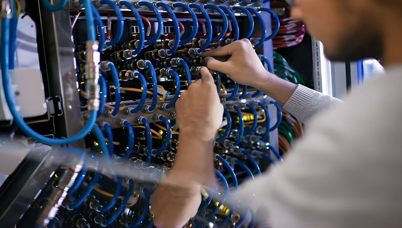
Industrial-grade fiber optic cables combine mechanical protection, chemical resistance, and optical performance in a single ruggedized package
1. What Is a Hybrid Fiber Optic Cable?
A hybrid fiber optic cable integrates two or more functional elements — most commonly optical fibers and electrical conductors — into a single cable structure. Rather than running a separate fiber data cable and a separate power or control cable in parallel, hybrid construction wraps both into one sheathed assembly designed for the same mechanical and environmental stresses.
The concept exists because real industrial systems are not simple. An ROV (Remotely Operated Vehicle) tether needs to carry high-bandwidth sensor data and drive power to thrusters at the same time, down hundreds of meters of seawater. A borehole seismic instrument string needs to transmit acoustic data from wellbore depths while withstanding crush pressure, hydrogen sulfide exposure, and continuous vibration from drilling equipment. A single combined cable is not just a packaging convenience — it is a fundamental engineering requirement for systems where adding cable bulk is impossible or where separate cable routing creates failure points no one can reach.
The Cost of Getting This Wrong
In oil & gas operations, unplanned fiber link downtime on a production platform can halt data acquisition from pressure sensors, flow meters, and safety monitoring systems. Restoration at depth or in confined topsides spaces can cost tens of thousands of dollars per incident. Specifying a cable based on price rather than environmental compatibility consistently produces that outcome within the first maintenance cycle.
Hybrid cables are not just an oil & gas product. They appear in any application that combines the need for optical data bandwidth with power delivery or electrical control signals, in an environment where mechanical simplicity and reliable performance matter more than absolute lowest cost per meter. That includes industrial robotics, subsea communications, ruggedized field deployments, military and defense systems, and heavy industrial automation.
2. Defining "Harsh": The Environments That Destroy Standard Cables
The word "harsh" gets used so broadly in industrial procurement that it has almost lost meaning. Before you can select the right cable, you need to be specific about what your environment actually does to a cable over time. The following categories cover the stressors that eliminate standard-grade fiber optic cables from contention:
| Stressor Category | What It Does to Standard Cable | Typical Environments |
|---|---|---|
| Sustained High Temperature | Softens PVC jacket, accelerates oxidation of conductor insulation, increases fiber coating brittleness over time | Furnace rooms, engine compartments, desert outdoor installations, wellbore instrumentation |
| Extreme Cold | Standard PVC jackets crack and shed at −20°C or below; frozen fibers lose flexibility and fracture under flexing | Arctic field installations, cold storage facilities, outdoor utility runs in northern climates |
| Chemical Exposure | Hydrocarbons, acids, solvents, and cleaning agents dissolve or swell PVC and standard thermoplastic jackets; corrodes metallic strength members | Oil & gas platforms, chemical plants, food processing facilities, hospital OR suites |
| Moisture and Submersion | Water ingress at termination points oxidizes copper conductors; gel-free fiber bundles wick moisture; hydrogen darkening degrades single-mode fibers over time | Marine, subsea, outdoor direct burial, wastewater treatment |
| Mechanical Abrasion | Repeated contact against machinery, cable trays, or conduit edges abrades jacket and exposes fiber buffer; high-cycle flexing fatigues standard aramid strength members | Robotics tethers, drag chain systems, continuously moving machinery |
| Crush and Lateral Load | Wheeled equipment or cable tray overload compresses fiber bundles below minimum bend radius, creating microbend losses that accumulate without visible external damage | Mining, tunneling, vehicle-traffic areas |
| Electromagnetic Interference (EMI) | Fiber itself is immune to EMI; however, copper conductors in hybrid cables without proper shielding pick up noise from variable frequency drives, welding equipment, and high-power motors | Manufacturing floors with heavy motor loads, welding cells, power substations |
The failure mode that catches most facilities teams off guard is not a single catastrophic stressor but the combination of two or more. An outdoor marine installation combines moisture, UV exposure, salt spray, and intermittent mechanical impact. A chemical plant cable tray combines chemical vapor exposure, elevated ambient temperature, and vibration from process equipment. Each stressor alone might be tolerable for a standard cable; together, they accelerate degradation geometrically.
3. How the MICE Framework Maps Your Environment to Cable Specs
The MICE classification system provides a structured method for characterizing harsh environments before selecting cabling. MICE stands for Mechanical, Ingress, Climatic/Chemical, and Electromagnetic — the four axes that define real-world installation conditions. Each axis is rated at three severity levels (M1/M2/M3, I1/I2/I3, etc.).
| MICE Letter | Element | What It Measures | Example Severity Jump |
|---|---|---|---|
| M | Mechanical | Vibration, impact, bend cycles, crush loads, tensile stress | M1: fixed installation; M2: occasional flex; M3: continuous high-cycle flex (robotics tether) |
| I | Ingress | Protection required against solid particles (dust) and liquid (water) penetration | I1: standard indoor; I2: drip/splash; I3: submersion or high-pressure wash-down |
| C | Climatic / Chemical | Temperature range, humidity, UV exposure, chemical contact | C1: office/controlled; C2: industrial range; C3: corrosive chemical or extreme thermal cycling |
| E | Electromagnetic | EMI/RFI field strength, electrostatic discharge, power line proximity | E1: typical office; E2: light industrial; E3: heavy motor plant or welding environment |
Mapping your installation against all four MICE axes before specifying cable turns an abstract "harsh environment" claim into a concrete list of required cable properties. A facility rated M3/I3/C2/E2 tells your cable supplier — and your procurement team — exactly what the cable jacket, water-blocking construction, temperature rating, and shielding need to deliver.
Practical MICE Assessment: Ask the People Who Work in the Space
The most accurate MICE rating for any installation comes from the maintenance and operations personnel who work there daily — not from the design drawings alone. Ask them:
- What cleaning chemicals are used and how frequently?
- Has any installed equipment been damaged by moisture, condensation, or flooding in the past 3 years?
- Are cables in the area subject to foot traffic, vehicle traffic, or contact with moving machinery?
- What is the highest and lowest ambient temperature the space reaches, including seasonal extremes and equipment heat loads?
- Are there welding operations, large VFDs, or high-power motors within 10 meters of the cable route?
The answers will frequently reveal environmental stressors that never appear in facility design documentation.
4. Jacket Materials: The First Defense Against Environmental Attack
The outer jacket is your cable's primary barrier between the harsh environment and the fiber core. Selecting the wrong jacket material for the chemical and thermal environment is the single most common cause of premature industrial cable failure. Here is a direct comparison of the materials your specification decision will come down to:
| Jacket Material | Temperature Range | Chemical Resistance | Flexibility | Best Application |
|---|---|---|---|---|
| PVC (Standard) | −20°C to +70°C | Low — attacked by many solvents, oils, and hydrocarbons | Good at room temperature; brittle in cold | Indoor, controlled environments only |
| LSZH (Low Smoke Zero Halogen) | −20°C to +70°C | Moderate — better than PVC for some chemical vapors | Moderate | Indoor spaces requiring fire/smoke compliance (data centers, transit, marine cabins) |
| TPE / TPU (Thermoplastic Elastomer/Polyurethane) | −40°C to +85°C | Good — resists oils, mild acids, greases, cleaning agents | Excellent — high torsional and bend flex life | Robotics tethers, drag chains, outdoor flex applications |
| XLPE (Cross-Linked Polyethylene) | −40°C to +90°C | Very good — resists chemicals, solvents, moisture | Lower than TPU; stiff in cold | Direct burial, outdoor utility, chemical environments |
| FEP / PTFE | −65°C to +200°C | Excellent — inert to virtually all chemicals and solvents | Limited — not suited for continuous flex | Downhole instrumentation, aerospace, high-temperature industrial sensors |
| Polyurethane (PUR) | −50°C to +80°C | Excellent — superior abrasion resistance; resists oils and fuels | Very good — designed for high-cycle flex and abrasion | Mining, offshore, robotic systems, any application with severe abrasion risk |
A cable rated for −40°C with a PUR jacket is not the same as a cable rated for −40°C with XLPE — the PUR cable will survive repeated coiling and uncoiling at that temperature where XLPE will crack. Specify both the temperature range and the expected mechanical behavior at temperature extremes.
Jacket material selection is the most critical variable in industrial cable longevity — the wrong material fails regardless of how well everything else is specified
5. Fiber Construction: Loose Tube vs. Tight-Buffered in Industrial Use
Inside the jacket, how the fiber strands are protected and organized has major implications for industrial performance. The two primary fiber bundle constructions — loose tube and tight-buffered — are suited to fundamentally different deployment scenarios.
5.1 Loose Tube Construction
In a loose tube cable, individual fibers or fiber ribbons are placed inside a thermoplastic tube larger than the fiber itself. The tube contains a gel (in gel-filled designs) or a dry water-blocking material. The gap between fiber and tube wall allows the fiber to move independently of the cable structure as it flexes or experiences thermal expansion and contraction.
Industrial advantages of loose tube:
- Fiber is mechanically isolated from strain events that stress the cable jacket — the fiber does not stretch when the cable does
- Gel filling (or dry water-blocking tape) prevents water migration along the cable length even if the jacket is breached
- Better suited for long outdoor or direct-burial runs where thermal cycling moves the cable repeatedly
- Higher fiber counts per cable cross-section compared to tight-buffered designs
Limitations: Loose tube fibers are not accessible without cutting the tube and cleaning away the gel — making in-the-field splicing slower and more difficult than tight-buffered alternatives. In applications requiring frequent breakout or field termination, loose tube cable adds labor cost.
5.2 Tight-Buffered Construction
In tight-buffered cable, each fiber is coated with a thick protective buffer layer (typically 900 μm) applied directly over the 250 μm fiber coating. There is no loose tube — the buffer is bonded directly to the fiber.
Industrial advantages of tight-buffered:
- Fibers can be broken out directly without cutting tubes or managing gel — ideal for multi-port termination panels and equipment rooms
- More compact overall cable diameter for a given fiber count compared to loose tube
- Better suited for indoor riser, conduit, and cable tray installations where installation length is moderate and temperature cycling is limited
- Fiber is accessible at any point along the cable for intermediate tapping or breakout
Limitations: Because the buffer transmits strain directly to the fiber, tight-buffered cables are more susceptible to fiber stress during installation if pulling tension or bend radius limits are violated. Not recommended for long outdoor or direct-burial runs where thermal expansion is a design factor.
Construction Decision Shortcut
If the run is outdoor, buried, subsea, or longer than 300 meters and subject to temperature swings → loose tube with gel-fill or dry water-blocking. If the run is indoor, in a conduit or cable tray, and requires accessible fiber breakout points along the route → tight-buffered distribution or breakout cable. Hybrid installations combining both is the norm in large industrial facilities.
6. Strength Members, Armoring, and Bend Performance
In harsh environments, optical performance is only as good as the cable's ability to survive the physical stresses of the installation and in-service life. Strength members and armor layers determine whether a cable survives being pulled through a conduit, dragged across a concrete floor, or run over by a forklift.
6.1 Strength Member Types
| Strength Member | Tensile Strength | Weight | Best Use |
|---|---|---|---|
| Aramid Yarn (Kevlar®) | High — 3,000 N typical for standard hybrid cable | Very low | General industrial, robotics tethers, lightweight hybrid cables |
| Fiberglass Rod (GRP) | Moderate — good crush and compression resistance | Low | Direct burial, outdoor aerial, static installations requiring anti-crush |
| Steel Wire Armor (SWA) | Very high — designed for trench, conduit, and subsea pulling loads | High | Direct burial, subsea, mining shaft, any route with rodent or crush risk |
| Stainless Steel Braid | High tensile with EMI shielding benefit | Moderate | ROV tethers, offshore platforms, applications needing both EMI shielding and tensile strength |
6.2 Armoring Options
Armor layers are distinct from strength members — they provide protection against external physical damage rather than tensile performance. The three most common armor types in industrial fiber cables are:
- Corrugated Steel Tape Armor (CSTA): Provides crush resistance and rodent protection for direct-burial and outdoor runs. The corrugation allows flexibility without compromising radial crush resistance.
- Interlocked Armor (Aluminum or Steel): Provides impact protection, flexibility under severe mechanical stress, and resistance to abrasion from sharp edges in conduit runs. Common in industrial process plant environments.
- Wire Braid Armor: Used in flex applications where armor must survive repeated bending cycles — ROV tethers and mining haul cables are the primary use cases. Wire braid tolerates flex where tape armor would eventually crack.
7. Application Profiles: Matching Cable Design to Industry
The following profiles summarize the cable specification priorities for the industrial sectors most commonly requiring ruggedized hybrid fiber optic cable:
7.1 Oil & Gas — Upstream and Topsides
Upstream oil & gas installations represent the full combination of environmental stressors: explosive gas atmospheres, H₂S and hydrocarbon chemical exposure, marine moisture and salt spray, extreme temperature variation from Arctic to desert conditions, and physical abuse from installation and maintenance crews working in confined spaces.
Cable specification priorities:
- ATEX/IECEx compliance for use in Zone 1 or Zone 2 explosive atmospheres where applicable
- Hydrogen-darkening resistant fiber — use G.654 or G.657 fiber types with enhanced coating systems for wellbore and high-hydrogen environments
- PUR or fluoropolymer jacket for hydrocarbon chemical resistance
- Armored construction (SWA or corrugated steel tape) for mechanical protection in topsides cable trays
- Operating temperature range: −40°C to +85°C minimum for outdoor surface installations; higher for downhole instrumentation (up to 200°C for logging applications)
7.2 Marine and Subsea
Subsea fiber optic cables face a unique combination of hydrostatic pressure (increasing at approximately 0.1 MPa per 10 m depth), constant moisture, bio-fouling, tidal mechanical forces, and in shallow water, ship anchor strikes and trawl damage.
Cable specification priorities:
- Water-blocking gel or dry-block construction to prevent moisture migration under pressure
- Polyethylene (PE) or PUR outer jacket for seawater chemical inertness
- Double wire armor for shallow-water or near-shore deployment where physical damage risk is highest
- Buoyancy tuning — for neutrally buoyant ROV tether designs, the cable core density must be matched to seawater density
- ROV umbilical hybrid cables combine single-mode fiber, electrical power conductors, and hydraulic hoses in a single integrated assembly
7.3 Industrial Robotics and Drag Chain Applications
Robotics tethers and drag chain cables represent the most mechanically demanding flex application in industrial settings. A cable in a drag chain may execute 10 million bend cycles over its service life. Standard aramid-reinforced fiber cables fail in this application — they are rated for static or occasional-flex use, not continuous high-cycle flex.
Cable specification priorities:
- Tight-buffered stranded fiber construction with individually supported fiber elements that flex independently
- PUR jacket — highest abrasion resistance of any practical cable jacket material, and rated for oil and coolant splash that is universal in robotic cells
- Torsionally balanced construction for cables that must both flex and rotate (articulated arm systems)
- Validated flex cycle certification — look for cables rated at a minimum 10 million cycles at the minimum bend radius for your drag chain geometry
7.4 Mining and Underground Infrastructure
Mining environments add the complication of explosive dust and gas atmospheres (coal dust and methane in underground coal mines), the constant risk of cable being run over by heavy equipment, and installation in water-filled tunnels where cable floats loose unless clamped at tight intervals.
Cable specification priorities:
- Armored design — SWA (Steel Wire Armor) is standard for mining backbone cables run along tunnel walls or conveyor frames
- Flame retardant jacket material tested to IEC 60332 standards — essential in underground environments where evacuation during a cable fire is extremely dangerous
- Water-blocking construction for flooded-tunnel installations
- Anti-static jacket compounds for coal dust environments (surface resistivity requirements per EN 50334)

Industrial fiber deployments require application-specific cable construction validated for the actual mechanical, chemical, and temperature demands of the operating environment
8. Installation and Maintenance in Harsh Environments
Even the best-specified cable fails in harsh environments when installation practices are careless. The mechanical damage most often responsible for early industrial fiber failure happens during the installation process itself — not in service.
8.1 Installation Best Practices
Pulling and Routing Rules
Never exceed the cable's rated minimum bend radius during installation — the dynamic bend radius (cable moving through a pull) should be 20× the cable outer diameter for standard industrial fiber; 30× for cables running in conduit with repeated pulling tension.
Respect maximum pulling tension limits — armored cables have higher rated pulling tension than unarmored, but pulling grip placement matters. Always attach pulling grips to the armor or strength member, never to the jacket alone. Exceeding tensile ratings during conduit pulls stretches aramid yarn and can induce permanent fiber strain that creates insertion loss invisible to a visual inspection.
Separate fiber and power cables in trays — fiber is immune to EMI but the metallic components of hybrid cables (copper conductors, armor) are not. Maintain at least 50 mm clearance from unshielded power cables in the same cable tray; use separate tray sections for fiber and power where possible.
Protect termination points from environment ingress — the most common moisture infiltration point in field-deployed fiber is not the cable itself but the termination enclosure seal. Verify all gland seals and connector housing IP ratings before closing the enclosure.
8.2 Maintenance Schedule for Industrial Fiber
| Frequency | Task | What to Look For |
|---|---|---|
| Monthly | Visual cable inspection along routing path | Jacket abraded or cracked sections, missing cable clamps, cables in contact with sharp edges or moving machinery |
| Quarterly | Optical power meter check on all critical links | Compare against baseline measurements taken at commissioning; ≥ 1 dB unexplained loss increase requires investigation |
| Semi-Annual | Termination enclosure inspection and seal check | Moisture ingress, corrosion on metallic components, degraded gland seals, contaminated connector end-faces |
| Annual | OTDR trace on all backbone runs | Compare trace to commissioning baseline; new reflection events indicate mechanical damage points; increased splice or connector loss indicates degradation |
The most important maintenance practice for industrial fiber is establishing a commissioning baseline: optical power measurements and OTDR traces taken immediately after successful installation, before the system goes live. Without that baseline, subsequent measurements have no reference point and gradual degradation is invisible until it causes a link failure.
9. Key Questions Answered
Q: What makes a fiber optic cable "hybrid" versus standard?
A: A hybrid fiber optic cable combines optical fibers with one or more additional functional elements — typically electrical power conductors, data conductors (copper), or both — within a single outer jacket assembly. Standard fiber optic cables contain only optical fibers and their strength members. Hybrid cables are specified when the installation requires both high-bandwidth optical data transmission and power delivery or electrical control signals to run along the same route, and when running two separate cables is impractical due to space, weight, or reliability constraints.
Q: How do I know if my installation environment qualifies as "harsh" for cabling purposes?
A: Apply the MICE classification framework: assess your installation on four axes — Mechanical stress (vibration, flex, crush, tension), Ingress risk (dust, water, pressure wash), Climatic/Chemical exposure (temperature range, chemical contact, UV), and Electromagnetic environment (proximity to motors, welding equipment, VFDs). Any axis rated at Level 2 or Level 3 indicates that standard cable construction is insufficient and industry-specific jacket material, armoring, or construction design is required. If you are uncertain, consult personnel who work in the space daily — they know the actual conditions better than design documents do.
Q: Why does PVC jacket material fail in oil & gas environments?
A: PVC is chemically attacked by hydrocarbons (crude oil, diesel, lubricating oils), aromatic solvents, and many cleaning agents common in oil & gas facilities. When exposed to these chemicals, PVC swells, softens, or becomes brittle — losing its mechanical protective properties. Additionally, PVC's temperature ceiling of approximately 70°C is below the ambient temperatures found in engine rooms and near heat exchangers. PVC cables in hydrocarbon environments typically show visible jacket degradation within 12 to 18 months, compared to 10+ year service life targets for infrastructure in those environments.
Q: What is the difference between loose tube and tight-buffered fiber construction for industrial use?
A: Loose tube construction places fibers inside thermoplastic tubes larger than the fiber, allowing the fibers to move independently of jacket stress and thermal expansion. Gel-filled loose tube cables also provide longitudinal water blocking. Loose tube is the preferred choice for outdoor, direct-burial, and long-run industrial installations. Tight-buffered construction bonds a thick 900 μm protective buffer directly to each fiber, making fibers accessible for field termination without tube cutting or gel cleanup. Tight-buffered cable is preferred for indoor conduit runs, equipment rooms, and any installation requiring accessible intermediate breakout points along the cable route.
Q: Do fiber optic cables in hybrid designs suffer from EMI in industrial environments?
A: The glass fiber itself is completely immune to electromagnetic interference — this is one of the primary reasons fiber displaces copper in high-EMI industrial environments. However, hybrid cables that include copper electrical conductors alongside the fiber are subject to EMI-induced noise on those copper elements. To address this, industrial hybrid cables for high-EMI environments incorporate individual conductor shielding (foil or braid) or an overall braid/foil shield over the complete cable assembly. The shielding must be properly grounded at both ends to be effective. The fiber data link remains unaffected regardless.
Q: What fiber type is recommended for downhole oil & gas instrumentation?
A: Downhole applications require fiber with enhanced resistance to hydrogen darkening — the absorption loss increase that standard G.652 single-mode fiber experiences when exposed to hydrogen gas at elevated temperature and pressure. ITU-T G.654 fibers (pure silica core) and specialty hermetic-coated fibers (with carbon or aluminum hermetic coating applied over the standard 250 μm coating) are specified for well logging and permanent downhole monitoring applications. At surface ambient conditions below 100°C, properly selected G.657.A2 fiber in a hermetic-coated construction provides the bend tolerance and hydrogen resistance needed for wellbore sensor strings.
Q: How many flex cycles can an industrial hybrid fiber cable be rated for?
A: Flex cycle ratings vary significantly by cable construction and are validated through standardized testing (e.g., IEC 60227, DIN EN 60811 series). Standard armored cables with aramid strength members are typically rated for static or occasional-flex service with no specified cycle count. Industrial flex cables designed for drag chain or robotic applications are typically rated at 5 to 20 million flex cycles at a specified minimum bend radius. For continuous-flex robotics applications requiring the highest service life, confirm with your supplier that cycle testing was conducted at the actual operating temperature, bend radius, and cycle frequency of your application — test data at room temperature and a generous bend radius can be misleading for Arctic or high-temperature robotic deployments.
Q: What standards apply to fiber optic cables for use in hazardous area (ATEX/IECEx) installations?
A: Fiber optic cables themselves do not carry electrical energy and are generally not subject to ATEX equipment certification requirements when only fiber elements are deployed. However, hybrid cables containing electrical conductors used in Zone 1 or Zone 2 (gas) or Zone 21 or Zone 22 (dust) hazardous areas must have their electrical components certified to ATEX Directive 2014/34/EU (or IECEx equivalent) for the applicable Equipment Category. The cable jacket and any metallic components must not generate electrostatic sparks — anti-static jacket compounds meeting EN 50334 surface resistivity requirements are required for cables in Zone 2 and Zone 22 environments. Always verify the full hazardous area zoning with your site safety engineer before specifying hybrid cables for upstream oil & gas or chemical plant applications.
Related Articles
- Fiber Optic Patch Cables: The Complete 2026 Buyer's Guide — Connector types, jacket ratings, and pull-proof designs for field and industrial termination points
- Armored vs. Unarmored Fiber Optic Cable: Your Complete Decision Guide for Enterprise Networks — Comparing SWA, interlocked armor, and unarmored constructions by environment and installation method
- Singlemode vs. Multimode Fiber: How to Choose for Industrial Networks — Distance, bandwidth, and cost tradeoffs for OS2 and OM3/OM4 in factory and plant deployments
- 10 Costly Fiber Optic Cable Installation Mistakes to Avoid in 2026 — Bend radius violations, improper pulling technique, and other field errors that destroy industrial fiber links

AMPCOM Technical Team
Industry experts with 17+ years in enterprise network infrastructure
Deploying fiber in a harsh or industrial environment?
AMPCOM supplies armored, ruggedized, and hybrid fiber optic cables engineered for oil & gas, mining, marine, and industrial automation applications. Our technical team provides free consultation and application-specific cable configuration.
Get Free Consultation

