AI Frontend vs Backend Networks: Key Design Differences in Data Center Architecture
Published:Executive Summary: AI data center network architecture is rapidly evolving due to the growing scale and complexity of AI workloads—large-model training and real-time inference are pushing traditional three-tier designs past their breaking point. Modern architecture is generally divided into two parts: the AI frontend network and the AI backend network. The frontend handles user access, application delivery, and north-south traffic. The backend supports GPU-to-GPU communication for distributed training and high-bandwidth east-west traffic.
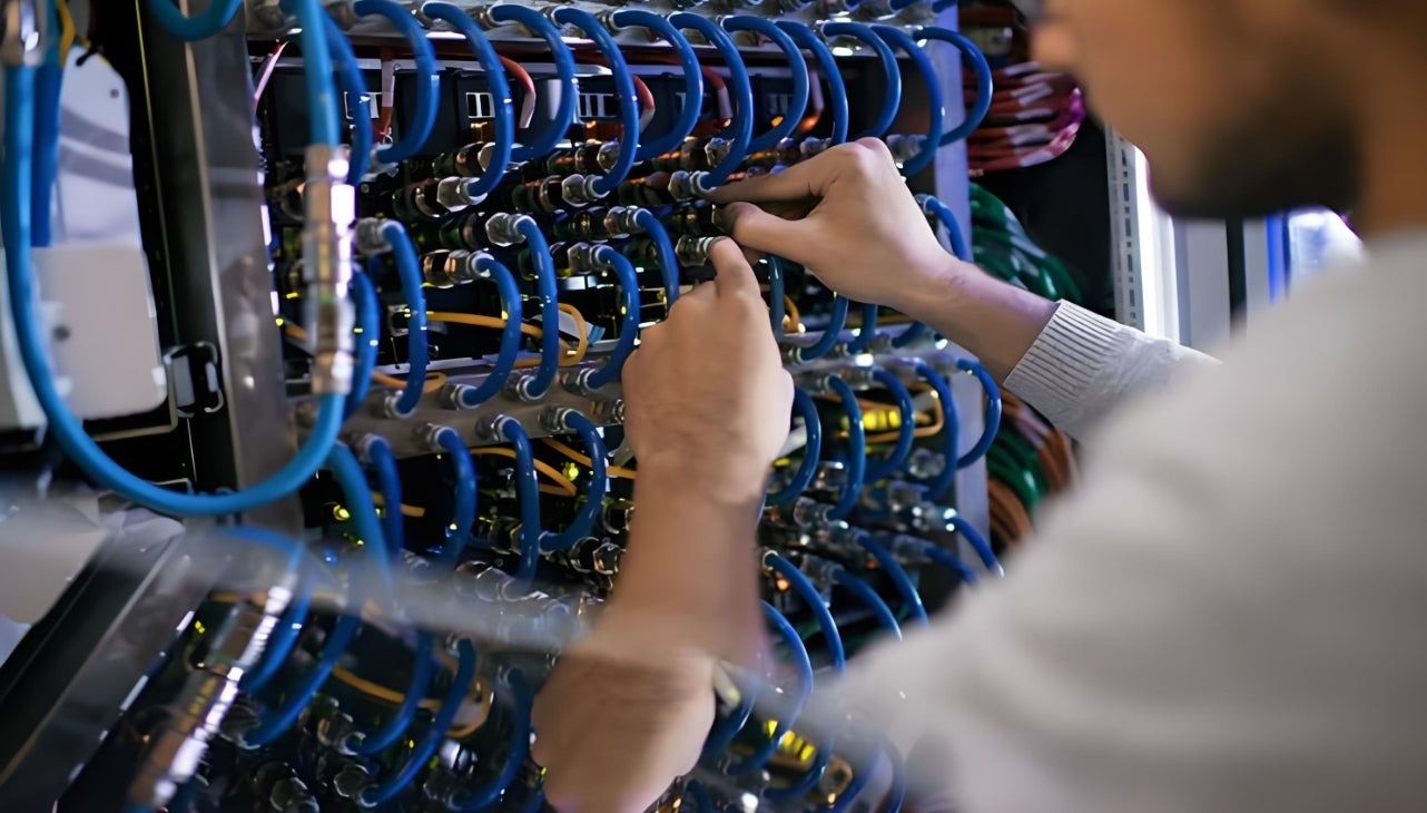
This separation allows each layer to be independently optimized. A 400G frontend link and a 400G backend link look identical to a cable, but they're carrying fundamentally different traffic patterns—and the cabling infrastructure must be designed with that difference in mind.
Quick Navigation
- 1 Understanding the AI Frontend Network
- 2 Understanding the AI Backend Network
- 3 Frontend vs Backend: Side-by-Side Comparison
- 4 Architectural Design Differences
- 5 Cabling Infrastructure for AI Networks
- 6 The Converged Ethernet Trend
- 7 AMPCOM Structured Cabling for AI Data Centers
- 8 Key Questions & Answers
AI data centers split into frontend and backend networks—each demands fundamentally different cabling strategies, from connector type to fiber density
1. Understanding the AI Frontend Network
The AI frontend network is the entry layer of an AI data center architecture, responsible for connecting external users, applications, and services to underlying compute and storage resources. It handles north-south traffic—all data that enters or leaves the AI system. In modern AI infrastructure, the frontend network acts as the control plane and data access layer, enabling communication between users and GPU/AI acceleration clusters.
AI frontend network traffic is characterized by small flows, high concurrency, burstiness, and mixed service types—demanding a design optimized for responsiveness, flexibility, and operational stability. Think of the frontend as the customer-facing storefront: users send inference requests, APIs ingest streaming data, and management tools monitor the cluster. Every query to a chatbot, every image submitted for processing, and every dashboard refresh traverses the frontend network.
1.1 Core Functions of the Frontend Network
The frontend network plays several critical roles in the overall AI data center architecture:
- User and service connectivity: Links external users, applications, and APIs to AI compute clusters, enabling access to inference and training services
- Data ingestion and preprocessing: Serves as the entry point for external datasets, streaming data, and enterprise workloads
- Model serving and inference support: Delivers real-time AI responses for applications such as recommendation systems, chatbots, and computer vision services
- Operational management and monitoring: Supports system-level communication, including scheduling, logging, checkpointing, and observability
1.2 Typical Hardware and Speed Requirements
AI frontend networks typically rely on standard Ethernet infrastructure built around the familiar leaf-spine architecture. CPU nodes connect at 100G, while spine-to-leaf links are rapidly migrating to 200G and 400G Ethernet. For management traffic and out-of-band access, standard 25G or even copper-based 10G connections remain common.
2. Understanding the AI Backend Network
The AI backend network is the core high-performance fabric of an AI data center, purpose-built to support east-west traffic between GPU and accelerator nodes. Unlike the frontend network, which focuses on service access and user connectivity, the backend network is dedicated to distributed training communication—enabling high-speed data exchange across large-scale GPU clusters. It acts as the critical infrastructure that connects thousands of GPUs into a unified, high-performance computing system.
If the frontend network is the storefront, the backend network is the factory floor. During a training run, hundreds or thousands of GPUs exchange gradient updates, parameters, and intermediate results constantly. Every millisecond a GPU spends waiting for data from another GPU is a millisecond of wasted compute—and at scale, those milliseconds compound into hours of lost training time.
2.1 Workload Characteristics That Define the Backend
AI backend workloads exhibit distinct traffic patterns that set them apart from frontend service traffic:
| Characteristic | Description | Why It Matters for Cabling |
|---|---|---|
| High-throughput, continuous communication | Driven by large-scale distributed training jobs; sustained and bandwidth-intensive rather than burst-oriented | Fiber links operate at near-saturation for minutes or hours—not seconds |
| Microsecond-level latency sensitivity | Even minor latency variations can significantly impact training efficiency and convergence time | Extra connector interfaces or excessive cable slack add measurable latency |
| Synchronous communication patterns | Training workflows rely on AllReduce, AllGather, and Broadcast operations | Any link failure stalls the entire training job—redundancy matters |
| Elephant-flow dominant behavior | Traffic composed of long-lived, high-volume data flows between GPU nodes | Bundled cables must avoid physical stress that could increase BER over time |
| Extreme sensitivity to packet loss | Loss or congestion triggers retransmissions, GPU idle time, and measurable slowdowns | Dirty connectors cause intermittent errors; inspection and cleaning protocols are essential |
2.2 Scale-Up vs. Scale-Out in the Backend Network
The backend network operates across two dimensions:
- Scale-Up (Intra-rack/Intra-node): Multiple GPUs within a single server or rack are interconnected through high-speed technologies such as NVIDIA NVLink, NVSwitch, and PCIe. This forms a high-bandwidth, low-latency communication domain that enables GPUs to share data directly without involving external network layers.
- Scale-Out (Inter-node): When training workloads extend beyond a single machine or rack, the backend network evolves into a distributed architecture connecting multiple GPU servers. At this layer, RDMA technologies dominate—GPUs bypass the OS kernel and directly access remote memory.
The two dominant implementations are InfiniBand and RoCEv2, both designed for lossless, high-throughput, and low-latency transport. InfiniBand, with its credit-based flow control that prevents packet loss at the source, currently holds a significant share of the GPU networking market. RoCEv2, running over standard Ethernet switches, is rapidly closing the gap as operators seek a unified fabric across frontend and backend.
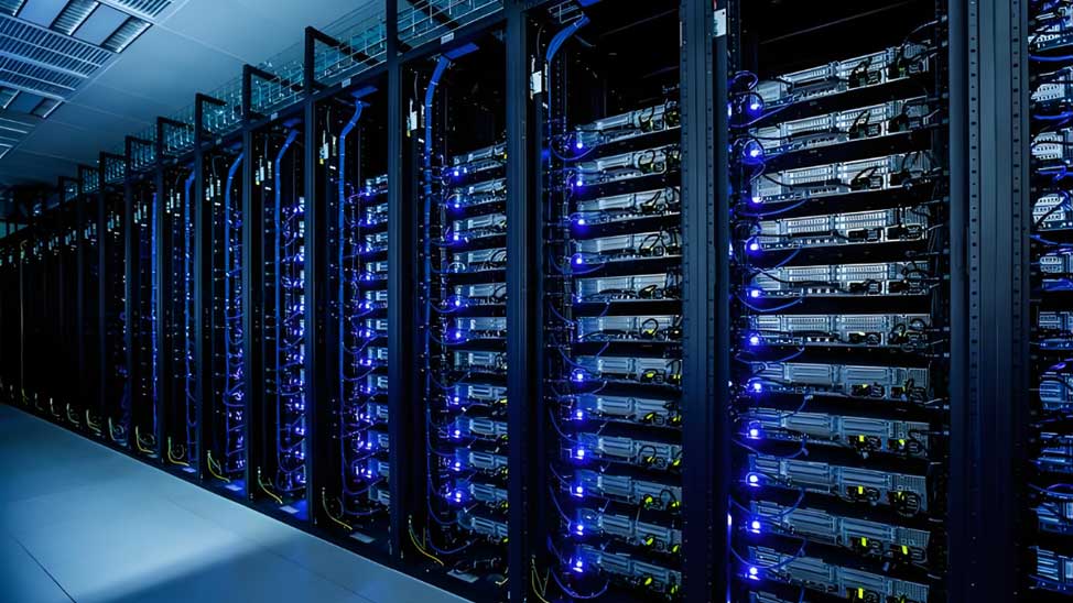
Backend AI training fabrics demand ultra-high-density fiber—up to eight times the fiber count of a traditional enterprise data center rack
3. Frontend vs Backend: Side-by-Side Comparison
Let's be clear about what separates these two network layers. The table below distills the critical differences into a single reference—keep it handy when you're mapping fiber counts for your next AI cluster build.
| Dimension | AI Frontend Network | AI Backend Network |
|---|---|---|
| Role | Service access and control layer | Distributed AI training fabric |
| Traffic Direction | North-south (in/out of the cluster) | East-west (GPU-to-GPU within the cluster) |
| Traffic Pattern | Small flows, high concurrency, bursty | Elephant flows, long-duration, synchronized |
| Typical Architecture | Ethernet leaf-spine (standard) | Hybrid: scale-up (NVLink/NVSwitch) + scale-out (InfiniBand or RoCEv2) |
| Main Nodes Connected | CPU servers, storage, load balancers, orchestration systems | GPU nodes, multi-node compute clusters |
| Performance Focus | Availability, stability, latency consistency | Ultra-low latency, high throughput, lossless transport |
| Key Technologies | VXLAN, EVPN, SDN, VLAN, WAF, API gateway | NVLink, RDMA, InfiniBand, RoCEv2 |
| Security Model | Strong isolation, multi-layer DMZ + firewall | Physically isolated; no external access |
| Bandwidth per Link | 25G–400G per server port | 400G–800G per GPU port |
Why Traffic Direction Changes Everything
In a traditional enterprise data center, north-south traffic dominates—clients request data, servers respond. In an AI training cluster, the ratio flips. An 8-GPU server performing distributed training can generate 8–16× more east-west traffic than north-south. The GPU-to-GPU gradient synchronization alone can saturate multiple 400G links continuously for the duration of the training run.
This traffic asymmetry is what makes the frontend-backend split necessary. Running both workloads on the same fabric would cause training traffic to starve inference requests, or vice versa. Physically separating them allows each side to be designed for its specific workload profile.
4. Architectural Design Differences
4.1 Frontend Network Architecture
The AI frontend network is typically built on a standard Ethernet leaf-spine architecture, integrating virtualized control mechanisms and layered security designs. Key characteristics include:
- VXLAN and BGP EVPN-based control plane: Enables flexible logical network construction, dynamic segmentation, and rapid service deployment without changing physical infrastructure.
- Service-oriented connection design: Interconnects CPU nodes, storage systems, load balancers, and orchestration platforms. Prioritizes low latency jitter and high availability over peak throughput, typically adopting dual-plane redundancy.
- Strong security and isolation: Strict logical or physical separation from backend training networks, implemented through VLANs, VXLAN segmentation, and SDN policies. API gateways and WAFs deployed at the entry layer provide unified access control and threat protection.
4.2 Backend Network Architecture
Unlike the frontend's service-access orientation, the backend network is designed for intensive east-west GPU-to-GPU traffic, supporting massive parallel computing workloads. The architecture can be summarized across two layers:
Scale-Up: Intra-Node and Intra-Rack Communication
Within a single server or rack, multiple GPUs connect through NVLink and NVSwitch—forming a high-bandwidth, low-latency domain that allows GPUs to share data directly without involving external network layers. This maximizes single-node performance, enabling multiple GPUs to operate as a unified compute block.
Scale-Out: Inter-Node Communication
When training extends beyond a single machine, the backend network shifts to a distributed scale-out architecture based on a spine-leaf or Clos topology. In this topology, each leaf switch connects to every spine switch, creating a uniform, non-blocking fabric where any GPU can reach any other GPU in a deterministic three-hop path: leaf → spine → leaf.
RDMA—via InfiniBand or RoCEv2—enables GPUs to bypass the OS kernel and access remote memory directly, reducing communication overhead. The choice between InfiniBand and RoCEv2 is increasingly driving architectural decisions across the entire cabling plant.
5. Cabling Infrastructure for AI Networks
The frontend-backend split in AI data centers doesn't just change switch architecture—it fundamentally reshapes the cabling plant underneath. Each side demands different connectors, different densities, and different fiber optimization strategies.
5.1 Fiber vs. Copper: Where Each Belongs
| Layer | Copper (Cat6A/Cat7/Cat8/DAC) | Fiber (OM3/OM4/OM5/OS2 + MPO) |
|---|---|---|
| Frontend: CPU ↔ Leaf | Cat6A/Cat7 for 10GBASE-T (up to 100m); Cat8 for 25GBASE-T/40GBASE-T (up to 30m) | Not typically needed at this layer unless runs exceed 100m |
| Frontend: Spine ↔ Leaf | DAC/AOC for short reach (≤ 5m); Cat6A for management ports | 400G-SR8/800G-SR8 with MPO-16 connectors |
| Backend: GPU ↔ Leaf | Not applicable | 400G/800G with MPO-12 or MPO-16 connectors (required) |
| Backend: Spine ↔ Leaf | Not applicable | 400G/800G with MPO-16 connectors; 1.6T on the horizon |
For most frontend access-layer deployments, Cat6A is the recommended minimum for 10G up to 100 meters, while Cat8 serves 25G/40G data center links within 30-meter reach. For a deeper comparison, see AMPCOM's guide on network cable categories.
5.2 MPO Connectors for Backend Density
At 400G and 800G, a single GPU interface can require 8 or 16 fibers. When a rack contains 4–8 GPU servers, each with 8 NICs, the fiber count per rack quickly reaches into the hundreds. MPO connectors solve this by consolidating 12, 16, or 24 fibers into a single compact interface.
AMPCOM's MPO fiber solutions guide explains how MPO trunk cables are used for structured backbone distribution between cabinets, zones, cassettes, and cross-connect areas—carrying multiple fibers in a clean, consolidated form across the infrastructure. MPO-24, for example, is purpose-built for 24-fiber parallel multimode optical transceiver applications at 400G and beyond.
5.3 Managing 800G Fiber: The Real Challenge
The real challenge at 800G is not simply supporting more optical bandwidth—it's preserving physical control after the fiber is installed. As port density escalates, cable congestion at the patch panel becomes the dominant operational risk.
Structured hardware such as cable managers helps preserve route separation and front-of-rack readability when patch density increases. For AI data centers, this is non-negotiable: when a training job worth millions of GPU-hours is running, no operator wants to trace a mislabeled fiber through a spaghetti rack.
At 800G, structured cabling with proper cable management is no longer optional—it directly impacts training job reliability and MTTR
6. The Converged Ethernet Trend
An important industry shift is underway: Ethernet is increasingly positioned as the technology of choice across both frontend and backend AI networks—not just the frontend. This convergence matters for cabling planners because it promises a unified physical infrastructure that simplifies procurement, spares management, and technician training.
The industry is seeing a rapid transition from 400G and 800G to 1.6T in a compressed timeframe to keep pace with GPU evolution, with Ethernet offering a consistent operational model across front-end, back-end, and management networks. RoCEv2, in particular, has emerged as the bridge technology—delivering InfiniBand-like RDMA performance over standard Ethernet switches.
For structured cabling design, this convergence trend has a practical implication: an AI data center built today with a converged Ethernet fabric should be planned for 800G port speeds at the spine layer, and prepared for 1.6T. That means specifying MPO-16 connectors at every fiber patch panel serving the backend, and ensuring bend-insensitive OS2/OM4 fiber is standard for all trunk runs.
7. AMPCOM Structured Cabling for AI Data Centers
Building an efficient AI data center requires more than just high-performance switches and GPUs—it demands a well-architected cabling infrastructure that supports the distinct needs of frontend and backend networks. AMPCOM's product portfolio addresses both layers with copper and fiber solutions designed for the density, speed, and reliability that AI workloads demand.
7.1 Fiber Infrastructure for the AI Backend
For backend GPU-to-GPU communication at 400G and 800G, AMPCOM provides a complete fiber optic system that includes MPO trunk cables, MPO-LC breakout assemblies, and high-density fiber patch panels. Key components include:
| AMPCOM Product | Configuration | Best Application |
|---|---|---|
| MPO/MTP Trunk Cable | OM3/OM4/OM5, 12/24 fibers, LSZH jacket, Type A/B available | Structured backbone distribution between cabinets, zones, and cross-connect areas |
| MPO/MTP Fiber Jumper | OM4 24-fiber, MPO UPC Female to Female, Magenta LSZH | High-density intra-rack patching; supports 24-fiber parallel multimode optics |
| High-Density ODF Panel | 12–144 ports, SC/LC/MPO adapter options, slide-out tray design | MDA backbones requiring front-access fiber termination and organized port mapping |
| 1U Horizontal Cable Manager | Finger duct with cover, 45×45mm spacing | Preserving route separation and front-of-rack readability at scale |
7.2 Copper Infrastructure for the AI Frontend
For frontend CPU-to-switch connections, out-of-band management, and storage networks, AMPCOM's copper product line provides reliable, standards-compliant connectivity:
| AMPCOM Product | Performance | Best Application |
|---|---|---|
| Cat6A S/FTP Shielded Cable | 500 MHz, 10G up to 100m | Enterprise frontend access layer; recommended minimum for new structured cabling |
| Cat7 S/FTP Shielded Cable | 600 MHz, 10G, double-shielded design | EMI-heavy environments, industrial data centers |
| Cat8 S/FTP Shielded Cable | 2000 MHz, 25G/40G up to 30m | Top-of-Rack to server; short-reach 25G/40G links |
| 1U 48-Port Keystone Patch Panel | Cat6/Cat6A-compatible, tool-less keystone | High-density rack termination; supports mixed copper/fiber modules |
Deployment Guidance: Frontend vs Backend Cabling Decisions
For the AI backend network: Standardize on MPO-16 trunk cables with OM4 or OS2 fiber. The backend demands lossless transport—every extra connector interface adds insertion loss that eats into your link budget. Use pre-terminated MPO assemblies where possible, and deploy structured cable management (1U horizontal managers, vertical managers) from Day 0. The fiber density in a GPU cluster is significantly higher than a standard enterprise rack; without structured management, maintainability collapses.
For the AI frontend network: For CPU-to-leaf connections, Cat6A S/FTP shielded cable is the recommended baseline—it supports 10G up to 100 meters and provides headroom for NBASE-T (2.5G/5G) as access speeds increase. For short-reach interconnects (spine-to-leaf within a rack row), DAC or AOC options typically prevail. AMPCOM's toolless keystone patch panels and 180° punch-down jacks enable IT teams to deploy and maintain ports rapidly with consistent, standards-compliant terminations.
8. Key Questions & Answers
Frequently Asked Questions About AI Frontend and Backend Networks
Related Articles
- MPO Fiber Solutions: Choosing 8, 12, or 24 Fibers for High-Density Cabling — Selecting the right MPO configuration for 400G, 800G, and 1.6T AI deployments
- Structured Cabling for AI Data Centers: What Is Changing — How AI workloads are reshaping density, interoperability, and infrastructure planning
- Cat6 vs Cat6a vs Cat7 vs Cat8: Which Cable Makes Sense for SMB Upgrades? — Matching cable categories to frontend access-layer speeds and distances
- MPO Fiber Solutions for Data Center and High-Density Cabling — Choosing 8, 12, or 24 fibers for AI cluster backbones and structured cabling

AMPCOM Technical Team
Field-tested guidance from structured cabling professionals with 15+ years in enterprise data center infrastructure and AI networking deployments
Planning an AI data center deployment?
AMPCOM's technical team provides free infrastructure consultation—from MPO trunk cable sizing to patch panel density planning. Tell us your GPU count and target port speeds, and we'll recommend the structured cabling configuration that minimizes installation time and maximizes long-term maintainability.
Get Free Technical Consultation

