
AI Data Center Fiber Optic Selection Guide: OM5, MPO & VSFF Connectors in Action
Published:Executive Summary: AI-driven high-density GPU racks are forcing data centers to upgrade beyond legacy fiber infrastructure. A single H100/H200 rack can demand 40–120 kW of power and 400–800 Gbps of internal bandwidth — thresholds that make OM3/OM4 and LC duplex connections obsolete. This guide breaks down three critical technology decisions: choosing the right fiber type (OM5 vs OS2), selecting the correct MPO connector architecture, and understanding where VSFF ultra-compact connectors fit. Includes practical guidance for 400G to 800G and 1.6T deployments in modern AI data centers.
Quick Navigation
- 1 Why AI Workloads Are Rewriting Fiber Requirements
- 2 OM5 Wideband Multimode Fiber: The AI-Optimized Workhorse
- 3 MPO/MTP Connectors: The Backbone of AI-Scale Cabling
- 4 VSFF Connectors: The Future of Ultra-Dense AI Cabling
- 5 Practical Selection Framework: Match Fiber to Deployment
- 6 The Bottom Line: Fiber Architecture Over Fiber Components

High-speed server rooms with AI GPU clusters require purpose-built fiber infrastructure — legacy OM3/OM4 and LC duplex connections cannot scale to 400G+ AI workloads
Chapter 1: Why AI Workloads Are Rewriting Fiber Requirements
The Bandwidth and Density Crisis
AI infrastructure is placing unprecedented demands on data center networks. A single high-density GPU rack — packed with 8×H100 or H200 GPUs — can consume 40–120 kW and require 400–800 Gbps of internal network bandwidth. Traditional OM3/OM4 multimode fiber and LC connectors, the backbone of 10-year-old data centers, simply cannot scale to these throughput requirements without expensive re-cabling.
The shift from "general-purpose computing" to "AI-first" infrastructure is creating three compounding challenges:
- Bandwidth explosion: GPU-to-GPU communication (east-west traffic) now dwarfs traditional north-south flows. A 128-GPU cluster requires full-bisection bandwidth — meaning every port must push multi-terabit aggregate throughput simultaneously.
- Density pressure: AI racks pack more compute per square foot than ever. Legacy LC duplex connections consume too much front-panel space. Each MPO 12-fiber connector replaces 6 duplex LC pairs.
- Thermal constraints: High-power AI racks generate 3–5× the heat of standard servers. Air cooling alone is often insufficient. Liquid-cooled racks demand tighter cable routing and smaller-form-factor connectors to avoid blocking coolant paths.
By 2027, over 65% of hyperscale data center ports shipped will be fiber-based at 400G or higher. Choosing the right fiber type and connector architecture today determines whether your infrastructure scales to the next GPU generation — or requires a costly full re-cabling project.
The core question is no longer "copper or fiber" — it is "which structured cabling for AI data centers architecture gives me the best density, reach, and future-proofing for my specific deployment?" Understanding fiber optic cable types and their wavelength capabilities is foundational to making the right choice.
Chapter 2: OM5 Wideband Multimode Fiber: The AI-Optimized Workhorse
What Makes OM5 Different from OM3/OM4?
OM5 fiber (ANSI/TIA-492AAAE) was specifically designed to support short-wavelength division multiplexing (SWDM), a technology that transmits multiple wavelengths over a single fiber strand to quadruple usable bandwidth without replacing the physical infrastructure.
Unlike OM3 and OM4, which are optimized for a single wavelength window around 850 nm, OM5 supports coherent transmission across the entire 850–950 nm window. This gives OM5 a decisive advantage in AI-scale deployments:
| Specification | OM3 | OM4 | OM5 |
|---|---|---|---|
| Effective Modal Bandwidth (EMB) | 2,000 MHz·km @ 850nm | 4,700 MHz·km @ 850nm | 3,500 MHz·km @ 850nm (SWDM-optimized) |
| Wavelength Support | 850nm / 1300nm | 850nm / 1300nm | 850–950nm (wideband window) |
| SWDM4 Support | Limited (≤40G per fiber) | Limited | ✅ Full SWDM4 (100G per fiber) |
| Max Distance @ 100G-SWDM4 | ~100m (degraded) | ~150m | 200–240m (full reach) |
| Typical Use Case | 10G / 40G Server ToR | 40G / 100G EoR | 100G–400G AI rack-scale interconnects |
| Cost vs OM4 | Baseline | +15–25% | +25–40% (but avoids re-cabling) |
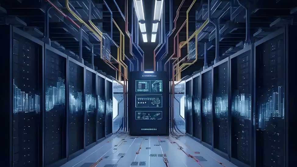
OM5 trunk cables with MPO connectors support parallel optic deployments at AI scale — the wideband window enables SWDM to quadruple bandwidth per fiber strand
When to Choose OM5 for Your AI Deployment
OM5 is the right choice when your switch-to-server distances fall in the 100–300 meter range — the sweet spot for most top-of-rack (ToR) and end-of-row (EoR) topologies inside a single data hall. It is particularly effective when:
- You're deploying 100G-SWDM4 or 200G-SR4 optics and need to future-proof for 400G-SR4.2
- You want to use existing OM3/OM4 infrastructure as a fallback path during migration
- Your AI racks are spaced across a single data center floor with typical 100–200m spans
⚠️ Common Mistake: Mixing OM5 with OM3/OM4
OM5 fiber is backward-compatible with OM3/OM4 optics at 850nm, but running OM3 patch cords in an OM5 trunk link will negate SWDM benefits and reduce reach. Always use OM5-grade patch cords and cassettes throughout the SWDM channel. A single OM3 patch cord in a 100G-SWDM4 link can drop the effective reach from 200m to under 80m. When upgrading to AI workloads, audit every fiber segment — the weakest link determines overall performance.
Chapter 3: MPO/MTP Connectors: The Backbone of AI-Scale Cabling
Why MPO Replaced Duplex LC in AI Data Centers
The MPO (Multi-Fiber Push-On) connector — standardized as IEC 61754-7 and TIA-604-5 — is the de facto termination standard for parallel optics in AI data centers. Where a single duplex LC link carries one 100G signal over two fibers, one MPO-12 connector carries 12 fibers simultaneously, enabling 100G-SR4 (4 fibers used) or 400G-SR4.2 (8 fibers used) with a single connector break-out.
The density math is compelling:
MPO Polarity: The Detail That Causes 50% of Network Failures
Polarity is the most misunderstood and most frequently mis-installed aspect of MPO cabling. In a parallel optics link, transmit (Tx) signals on one end must connect to receive (Rx) ports on the other. Three standardized polarity methods exist:
| Method | How It Works | Pros | Cons | Best For |
|---|---|---|---|---|
| Method A (Key-up/key-down) | Key-up on both ends, fiber flips via adapter | Simple, widely supported | Requires key-flip adapters | Single-row trunk links |
| Method B (Key-up/key-up) | Key-up on one end, key-down on other; straight-through adapter | No special adapters needed | Requires different trunk on each end | Row-by-row structured cabling |
| Method C (Pair-flip) | Adjacent fiber pairs swapped in trunk | Universal patch cords | Harder to troubleshoot; less common | Legacy migration projects |
AMPCOM Best Practice
Standardize on Method B polarity for all new AI data center builds. Document the polarity method in your as-built drawings and label all MPO cassettes with Tx/Rx fiber assignments. A single polarity misconfiguration can take down an entire rack's GPU interconnect fabric during commissioning — costing hours of expensive GPU compute time.
MPO-12 vs MPO-24 vs MPO-16: Which to Choose?
| Connector Type | Primary Use Case | Optics Support | Best Deployment |
|---|---|---|---|
| MPO-12 (12-Fiber) | Standard for 40G/100G SR4 | 400G-SR4.2 (8F used) | ToR and EoR switch uplinks |
| MPO-16 (16-Fiber) | Emerging for 200G-SR4 | 800G-SR8 (8 pairs) | 800G leaf switches |
| MPO-24 (24-Fiber) | Hyperscale core fabric | 400G-SR4.2 / 1.6T SR8.2 | Future-proof spine and leaf |

High-density MPO-based structured cabling in a modern AI data center — each MPO trunk replaces 6 duplex LC connections, dramatically reducing cable bulk and improving airflow
Chapter 4: VSFF Connectors: The Future of Ultra-Dense AI Cabling
What Are VSFF Connectors?
Very Small Form Factor (VSFF) connectors — including SN, MDC, and CS — represent the next evolution in fiber connectivity, packing 4–8 connections into the space previously occupied by a single LC duplex port. As AI racks push toward 800G and 1.6T switch ports with 64×100G channels, VSFF connectors are becoming essential for maintaining manageable cable routing.
VSFF connectors are specifically designed for blade server and GPU sled front-panel deployments where physical space is at a premium and liquid cooling manifolds leave no room for bulky LC duplex boots.
| Feature | LC Duplex | MDC | SN | CS |
|---|---|---|---|---|
| Footprint per port | 6.25mm wide | 3.1mm (2× density) | 3.5mm (1.8× density) | 4.5mm (1.4× density) |
| AI rack suitability | ❌ Legacy plane only | ✅ ToR AI switches | ✅ GPU sled front panels | ⚠️ Transition phase |
| Liquid cooling compatible | ❌ Boot blocks manifolds | ✅ Low-profile boot | ✅ Low-profile boot | ✅ Compact ferrule |
| Availability | Universal | Growing rapidly | Emerging (Senko) | Limited enterprise |
Industry Trend
NVIDIA's GB200 NVL72 rack-scale system ships with MDC-style connectors as the standard GPU sled interface. If you're designing infrastructure for next-generation GPU clusters (post-H200), planning for MDC or SN compatibility is no longer optional — it is a baseline requirement. Review your structured cabling for AI data centers design to ensure VSFF compatibility from day one.
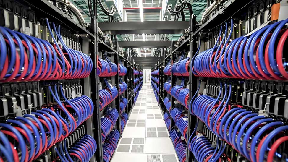
VSFF connectors with low-profile boots are essential for liquid-cooled AI racks where cable routing must not interfere with coolant manifold seals
When to Deploy VSFF
- GPU sled front panels: NVIDIA GB200 and AMD MI300X sleds have shifted to MDC or SN interfaces. Plan VSFF-compatible patching infrastructure from day one.
- Ultra-dense switch line cards: 128×100G QSFP-DD line cards with 1U front panels require MDC or SN to achieve usable port density without cable congestion.
- Liquid-cooled racks: VSFF connectors with low-profile boots don't block coolant manifold seals — critical for direct liquid-cooled (DLC) deployments.
- Migration strategy: Use VSFF in new builds while maintaining MPO backbone infrastructure. VSFF ports on switches can be broken out from MPO trunk via hybrid patch panels.
Real-World Case: Hyperscale AI Cluster Cabling Migration
Scenario: A 50MW data center in Northern Virginia upgraded from 40G OM3 infrastructure to support 400G AI GPU clusters. The original design used LC duplex patch panels across 120-meter horizontal runs.
Solution: Deployed OM5 trunk cables with MPO-12 cassettes (Method B polarity) to consolidate 6× duplex links per MPO trunk. Replaced existing LC panels with MPO-to-LC cassette panels in the EoR position, keeping existing server LC patch cords in place. Added MDC fan-out panels for new GPU sleds.
Result: 60% reduction in cable bulk, 40% improvement in airflow, and a fully future-proofed infrastructure ready for 800G migration without re-cabling the backbone.
Chapter 5: Practical Selection Framework: Match Fiber to Deployment
Use this decision framework to select the right fiber and connector combination for your specific AI data center scenario:
📋 AI Data Center Fiber Selection Checklist
- Distance & optics type: Measure the longest switch-to-server span. OM5 handles 200–240m @ 100G-SWDM4. Singlemode OS2 handles 10km+. Choose the fiber grade that matches your primary optics wavelength.
- Port density target: If rack unit efficiency matters, commit to MPO-12 or higher. Every 1U of switch front panel saved is rack space for additional compute.
- Migration path: Design for a 2-generation optics roadmap. If you're deploying 400G today, plan the infrastructure so 800G optics can be dropped in without re-cabling.
- Polarity method: Choose one standard (recommend Method B), document it, and enforce it across all vendors and installers. Polarity errors are the #1 cause of MPO link failures.
- Testing requirements: MPO trunk links require Encircled Flux (EF) compliant launch conditions per TIA-526-14-C. Specify EF-compliant test sources for all Tier-1 certification.
- GPU sled compatibility: Confirm the GPU vendor's recommended front-panel connector type. NVIDIA GB200 = MDC. AMD MI300X = typically LC or MDC. Plan backward-compatible patch panels accordingly.
📊 Fiber Selection Quick Reference Table
| Scenario | Recommended Fiber | Recommended Connector | Key Rationale |
|---|---|---|---|
| AI ToR: 100–200m, 400G-SR4 | OM5 | MPO-12 (Method B) | Cost-effective, high density, SWDM-ready |
| AI EoR: 200–300m, 100G-SWDM4 | OM5 + OS2 hybrid | MPO-12 + LC duplex | OM5 for short-haul, OS2 for DCI |
| GPU sled front panel (NVIDIA GB200) | OM5 or OS2 | MDC or SN | Native GPU sled interface; future-proof |
| 800G leaf switch uplink | OM5 (≤200m) or OS2 | MPO-16 or MPO-24 | 8-fiber SR8 optics require MPO-16 |
| 1.6T spine fabric (2027+) | OS2 (long-haul), OM5 (short) | MPO-24 or emerging VSFF | Plan MPO-24 backbone for 1.6T SR8.2 |
Q&A: Your Fiber Selection Questions Answered
❓ Can I use existing OM3/OM4 infrastructure for AI GPU clusters?
Possibly for short 40G links under 100m, but OM3/OM4 cannot support 100G-SWDM4 beyond 100–150m without significant signal degradation. For any AI deployment at 100G or above with distances over 100m, OM5 is the minimum recommended grade. Reusing legacy fiber is a false economy when a single link failure during a critical training run can cost hours of expensive GPU compute time.
❓ OM5 or singlemode OS2 for AI rack interconnects — which wins?
For distances under 300m (the vast majority of intra-data-center AI deployments), OM5 with SWDM optics is significantly more cost-effective than singlemode. OS2 becomes the clear choice for inter-data-center links over 2km, DCI (Data Center Interconnect), or campus-wide AI fabric. Most AI clusters use an OM5 spine + OS2 leaf architecture.
❓ MPO connectors seem fragile — how do I ensure long-term reliability?
MPO reliability comes down to three factors: (1) Use APC-grade MPO connectors with 8° angled endface — they resist dust and reflection better than UPC. (2) Clean MPO connectors before every mating cycle using proper reel-type cleaners — never use isopropyl alcohol swabs on MPO endfaces. (3) Specify MPO adapters with floating sleeves for high-vibration environments. Follow IEC 61300-3-35 for inspection criteria.
❓ When should I jump to VSFF instead of sticking with MPO/LC?
Transition to VSFF when: (a) your switch line cards ship with VSFF-native ports (most 128×100G QSFP-DD cards launched in 2025+ support MDC); (b) you have liquid-cooled racks where LC boot height blocks coolant manifolds; or (c) you are deploying new GPU clusters post-2026. For existing 400G deployments with MPO infrastructure, there is no urgency — VSFF patch panels are backward-compatible via hybrid modules.
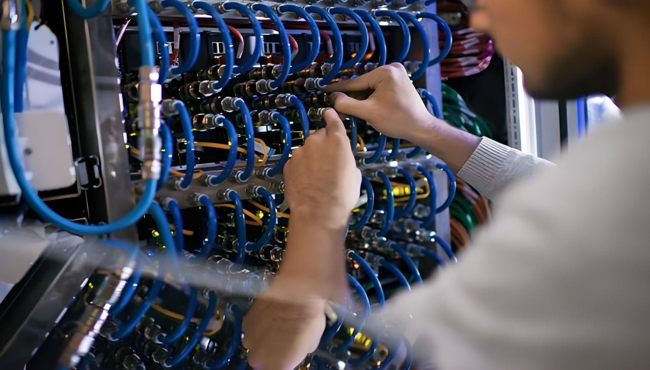
Tier-1 certification testing of MPO trunk links requires Encircled Flux (EF) compliant test sources per TIA-526-14-C — proper testing prevents costly failures at AI workload commissioning
Chapter 6: The Bottom Line — Fiber Architecture Over Fiber Components
AI infrastructure is not a fiber upgrade problem — it is a fiber architecture problem. The data centers that invest in fiber architecture clarity today will be the ones that scale to 1.6T without cable chaos. OM5 gives you the bandwidth and reach for AI-class multimode distances. MPO-12 gives you the density to make AI-scale cabling manageable. VSFF gives you the flexibility to connect the next generation of GPU sleds without redesigning your backbone.
Start with OM5 + MPO-12 as your foundation, plan for OS2 extension at 2km+, and watch the GPU vendor roadmaps for VSFF adoption timelines. The critical actions are:
🚀 Immediate Action: Audit your current fiber infrastructure — identify every OM3 segment and every duplex LC link that will become a bottleneck under AI workloads.
📐 Architecture Decision: Choose OM5 for intra-data-center runs under 300m, commit to MPO-12 Method B polarity, and plan your OS2 extension path for DCI and long-haul.
🔮 Future-Proof: Track GPU vendor roadmaps (NVIDIA GB200 = MDC; AMD MI300X = MDC/LC) and design patch panels that support hybrid MPO-to-VSFF break-outs from day one.

AMPCOM Technical Team
Industry experts with 17+ years in structured cabling, data center infrastructure, and fiber optic network design
Need help selecting the right fiber infrastructure for your AI data center?
AMPCOM provides a full range of structured cabling solutions — including OM5 fiber cables, MPO/MTP cassettes, VSFF (MDC/SN) connectors, and high-density patch panels designed for AI-scale deployments.
Talk to Our Infrastructure Experts

