
AI Cluster Cabling in Practice: MPO Polarity, Insertion-Loss Budgets & Rapid Deployment Guide
Published:Executive Summary: The same MPO trunk that passed every factory test can still come up "dark" in the rack — and the same link that was bulletproof at 10G can fail silently at 800G. Two things explain almost every AI-cluster cabling incident: MPO polarity (transmit never reaching receive) and insertion-loss budget (the margin that 400G/800G quietly eats). With the industry now migrating from MPO-12 to MPO-16 / MMC for 800G→1.6T and densities hitting 3,456 fibers per 1U, getting polarity and the loss budget right at the BOM — not in the rack row — is the whole game. This Installation Hub guide gives you the field playbook.
Quick Navigation
- 1 MPO Polarity — The Silent Killer: Green in the Factory, Dark in the Rack
- 2 Insertion-Loss Budgets — Why 400G/800G Leaves No Margin
- 3 Base-8 vs Base-12 vs Base-16 — Fiber Count for the AI Era
- 4 Rapid Deployment — Pre-Terminated MPO Trunk + Cassette Playbook
- 5 End-Faces, Bend Radius & First-Pass Yield
- 6 Case Study — 64-Rack Cluster That Fixed Polarity at BOM Time
- 7 Key Takeaways — The MPO Do / Don't Summary
- 8 Frequently Asked Questions

High-density AI clusters push MPO connector counts into the thousands per rack — and with them, the polarity and loss-budget risk that legacy 10G builds never had to manage
Chapter 1: MPO Polarity — The Silent Killer: Green in the Factory, Dark in the Rack
A link has correct polarity when the transmitter (Tx) at one end lands on the receiver (Rx) at the other. An MPO connector carries 8, 12, 16, or 24 fibers in a single ferrule, and the only thing that decides which fiber maps to which is the key orientation and the internal fiber sequence of every component in the chain. Change any one of them without changing the rest, and you get a link that passes loss testing but never passes traffic.
This is why polarity failures are so infuriating: the link is optically perfect, the OTDR is clean, the loss is in budget — and the port light stays dark. There is no "almost" with polarity. It is correct or it is not.
1.1 The Three Connector Types (A / B / C)
Polarity is defined by how the fibers are wired inside the MPO and how the key sits:
| Type | Key Orientation | Fiber Mapping | Effect |
|---|---|---|---|
| Type A (straight-through) | Key-up → key-up | 1→1, 2→2 … 12→12 | No flip — Tx stays on Tx position |
| Type B (reversed) | Key-up → key-down | 1→12, 2→11 … 12→1 | Full reversal — flips Tx/Rx |
| Type C (pair-flip) | Key-up → key-up | 1↔2, 3↔4 … 11↔12 | Adjacent pair flip — for duplex |
1.2 The Three Deployment Methods (TIA-568)
The trunk type and the cassette / patch-cord type must be chosen as a set. Mixing Method A and Method B components is the single most common cause of a "dark" AI link:
| Method | Trunk | Cassette Module | Patch Cord | Typical Use |
|---|---|---|---|---|
| A | Type A (straight) | Type A (internal flip) | Straight | General duplex + SR4 via modules |
| B | Type B (reversed) | Straight (no flip) | Straight | Direct 40G/100G/400G SR parallel optics |
| C | Type C (pair-flip) | Straight | Straight | 10G duplex breakouts |
⚠️ The #1 polarity mistake: A Method A cassette installed in a Method B system (or vice-versa) puts Tx on Tx. The link tests green and carries zero traffic. The fix is never in the field — it is a re-ordered BOM. Lock the method in the design room and stamp it on every cassette, trunk, and harness label.
1.3 Don't Forget Gender and the Key
MPO connectors are male (with guide pins) or female (without). A pinned connector only mates with an unpinned one — two males or two females will not click together, and if forced, they shear the alignment pins. In a typical structured channel the rule is: trunk = male-to-male; cassette = female receptacle; transceiver-side harness = male-to-female. Gender errors are caught at install (they physically won't mate), but the downtime and re-order cost are real. Key orientation (key-up vs key-down) is the quieter cousin of the same problem and is not caught by eye.
Q: If a link tests clean on loss, can polarity still be wrong?
A: Absolutely — and it usually is. Loss/OTDR testing confirms the fiber is continuous and within budget; it says nothing about whether fiber 1 at the switch reaches fiber 12 at the GPU (where Rx lives). Polarity is a wiring-logic problem, not an optical-loss problem. The only reliable field check is a continuity / Tx-Rx verification with a light source and a polarity meter, or simply reading the BOM method off every label before mating. Build the method into the labeling scheme and you never reach for the meter.

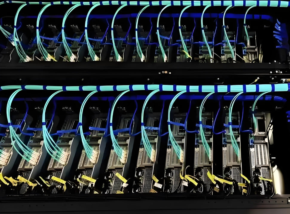
A high-speed AI network center — every MPO in this hall shares one polarity method, stamped on the label, or the whole fabric goes dark
Chapter 2: Insertion-Loss Budgets — Why 400G/800G Leaves No Margin
At 10G over OM4 you had ~3.0–3.5 dB of channel budget and connectors that lost 0.5 dB each felt fine. At 400G and 800G that same slack vanishes. The optics get faster, the launch power does not grow proportionally, and the loss budget tightens to the point where connector choice — not fiber length — becomes the limiting factor.
2.1 Representative Channel Loss Budgets (multimode, per the optics standard)
These are typical IEEE 802.3 channel insertion-loss (IL) limits for parallel multimode optics. Always read the exact number off the transceiver datasheet — treat the table as planning guidance, not a substitute for the spec:
| Optic | Fiber | Reach | Channel IL Budget | Connectors That Fit |
|---|---|---|---|---|
| 100GBASE-SR4 | OM4 | 100 m | ~3.5 dB | Standard or low-loss |
| 400GBASE-SR4.2 | OM4 | 100 m | ~2.9 dB | Low-loss only |
| 400GBASE-SR8 | OM4 / OM5 | 100 m | ~3.0 dB | Low-loss only |
| 800G (SR8 / SR4.2) | OM4 / OM5 | 60–100 m | ~2.0–2.6 dB | ELITE / ultra-low-loss |
2.2 Build the Budget Before You Buy
A channel loss budget is the sum of every mated connection, every splice, the fiber attenuation, plus a design margin you never spend:
📐 Budget = Σ(connector IL) + Σ(splice IL) + (fiber length × attenuation/km) + design margin
Reference losses: OM4 attenuation ≈ 3.0 dB/km at 850 nm (so 100 m ≈ 0.30 dB); a calibrated standard MPO mate ≈ 0.50 dB; a low-loss MPO ≈ 0.35 dB; an ELITE MPO ≈ 0.20 dB; a fusion splice ≈ 0.30 dB.
Now run a realistic structured channel for 400G SR4.2 over OM4, 100 m. The permanent layer uses two cassettes joined by one trunk, with a patch cord at each end — that is 6 mated MPO connections plus 100 m of fiber:
| Component | Standard MPO (0.50) | Low-Loss (0.35) | ELITE (0.20) |
|---|---|---|---|
| 6 × mated MPO connectors | 3.00 dB | 2.10 dB | 1.20 dB |
| 100 m OM4 fiber | 0.30 dB | 0.30 dB | 0.30 dB |
| Total | 3.30 dB | 2.40 dB | 1.50 dB |
| Budget (2.9 dB) | ❌ Over by 0.4 dB | ✅ 0.5 dB margin | ✅ 1.4 dB margin |
That single table is the whole argument for low-loss MPO: with standard connectors, a perfectly normal 6-connection channel fails 400G before you add a single meter of fiber or a dust speck. At 800G the budget is ~2.0–2.6 dB, so low-loss is the floor and ELITE is the safe choice. The connector grade is a BOM decision, not a field rescue.
Q: My 10G links used 0.5 dB MPO and were fine — why change now?
A: Because the budget moved, not the connector. A 10G OM4 channel at ~3.5 dB tolerates six 0.5 dB mates with room to spare. A 400G channel at ~2.9 dB does not — six 0.5 dB mates alone (3.0 dB) blow the budget before fiber is counted. The faster the optic, the more each mated connection matters. That is why 400G/800G deployments standardize on low-loss (0.35 dB) and ELITE (0.20 dB) MPO: it is the only way to keep margin for end-face dust, an inevitable re-mate, and a 50 m pull instead of a 30 m one.

Fluke certification — every 400G/800G link must be verified against its specific loss budget, not a generic pass/fail, before a GPU goes live
Chapter 3: Base-8 vs Base-12 vs Base-16 — Fiber Count for the AI Era
The fiber count inside the MPO ferrule decides how many lanes you get and how cleanly you migrate from 100G to 800G to 1.6T. The industry is mid-migration, and the wrong base today is a forklift upgrade tomorrow.
| Base | Fibers | Best For | AI-Era Verdict |
|---|---|---|---|
| Base-8 | 8 | 40G/100G SR4 (4 lanes × 2) | Most efficient for 100G; clean 2× scale to 400G |
| Base-12 | 12 | Legacy 10G/40G; 100G uses 8 of 12 | 4 fibers wasted at 100G+; still installed base |
| Base-16 / MPO-16 | 16 | 400G (8×50G) and 800G (16×50G) | The AI-cluster standard; one connector per 800G |
💡 The migration logic: 800G most often uses 8 fibers (SR8) or 16 fibers (SR4.2 / 16×50G). Base-8 scales to 400G cleanly (one Base-8 = 100G, two = 400G) and to 800G with a single MPO-16. Base-12 strands four idle fibers at every 100G port and complicates 800G mapping. For new AI builds in 2026, specify Base-8 trunks with an MPO-16 upgrade path — or go straight to MPO-16 where 800G/1.6T is on the roadmap. The newer MMC / VSFF interface carries the same density in roughly a third of the footprint (≈3,456 fibers per 1U), which is why hyperscalers are standardizing on it.
Q: I have a Base-12 plant today. Do I rip it out for 800G?
A: Not necessarily. Base-12 can carry 100G (8 fibers used) and, with breakout cassettes, map to 400G. For 800G you have two realistic paths: (1) re-map existing Base-12 trunks through cassettes that aggregate to 800G, accepting some pin waste, or (2) overlay MPO-16 trunks in the same pathway for the 800G/1.6T tier. The cheaper play is to freeze Base-8 as the new-build standard and let MPO-16 handle the next speed step — so the question becomes "what do I buy next", not "what do I tear out". Plan the fiber count at BOM time and the 1.6T jump is a cassette swap, not a rebuild.
Fiber count planning — Base-8 with an MPO-16 path is what lets an AI cluster ride 100G → 400G → 800G → 1.6T without a forklift upgrade
Chapter 4: Rapid Deployment — Pre-Terminated MPO Trunk + Cassette Playbook
Speed and correctness are the same decision. The way you avoid polarity and loss-budget surprises in the rack row is to decide them in the factory. A structured cabling build separates the permanent backbone (pre-terminated MPO trunks + cassettes) from the variable patch layer (short factory-made jumpers) — and that separation is what lets an AI cluster deploy in weeks, not seasons.
4.1 Pre-Terminated Trunk + Cassette vs Field Termination
| Dimension | Field Fusion Splicing / Patching | Pre-Terminated MPO Trunk + Cassette |
|---|---|---|
| Per-technician throughput | ~12–20 terminations / shift | 24–288 fibers per 10-min mate |
| First-pass yield | 70–85% (site variables) | 99%+ (factory-controlled) |
| Polarity assurance | Set by installer, error-prone | Built & verified at factory, labeled |
| Loss-budget risk | High — varies per joint | Low — ELITE/low-loss, tested |
| Schedule at 8,000 fibers | ~14 weeks termination | Near-zero field termination |
4.2 The Three Things to Freeze Before the Factory Order
Pre-Terminated BOM Freeze Checklist
1. Polarity method: Lock Method A or B across every cassette, trunk, and harness. Stamp it on every label. This is the anti-"dark link" control.
2. Connector grade & fiber count: Specify low-loss / ELITE MPO and Base-8 (MPO-16 path) or MPO-16. This is the loss-budget control — and it decides whether 400G/800G will even close.
3. Lengths & labeling: Every trunk length and port code to TIA-606-B, baked into the factory build. Change orders after PO cost 3–5× more than the equivalent field change.
✅ What Deploys Fast & Clean
- One polarity method, stamped on every label
- Low-loss / ELITE MPO in the BOM
- Pre-terminated, factory-tested trunks
- 10-minute mate; verify Tx-Rx at handover
❌ What Sends You Back to the Rack
- Mixed Method A / B cassettes
- Standard 0.5 dB MPO on 400G+ links
- Field-terminated trunks on a 6-month clock
- Late BOM changes after factory PO
Q: Doesn't pre-termination lock me into a design I can't change later?
A: Only if you freeze the wrong thing. The structured approach keeps the permanent trunk generic (MPO trunks between fixed zones) and pushes variability into the patch layer (short LC/MPO jumpers you re-map freely). MPO trunks are rated for 200–500 mate/de-mate cycles, so re-patching is routine. What you must freeze is the polarity method, connector grade, and trunk lengths — and a fast-track schedule forces you to freeze those anyway. Pre-termination trades flexibility in the permanent layer for correctness and speed, which is exactly the trade AI clusters need.

Pre-loaded cassettes and pre-tested MPO trunks turn rack rows into drop-in units — polarity and loss budget decided in the factory, not the aisle
Chapter 5: End-Faces, Bend Radius & First-Pass Yield
Fast deployment is not reckless deployment. The two failure modes that surface weeks later — both invisible at install — are contaminated end-faces and bend-radius violations. In dense AI racks, over-long patch cords are the leading cause of tight bends that quietly kill 400G+ signal integrity.
🧼 End-Face Cleaning SOP
- Clean + inspect (scope) before every mate
- Dust is the #1 cause of return-loss spikes at 400G+
- Cap every unused ferrule; never touch the tip
📐 Bend Radius & Pull Force
- Min bend ≥ 30 mm for OM4; ≥ 50 mm for trunk bundles
- Pull force ≤ 100 N for 12-fiber MPO
- Use a patch-cord length matrix (1/2/3/5 m) to avoid slack
🔍 First-Pass Yield Gate
- OLTS every link against its specific budget
- Re-mate + re-clean before condemning a trunk
- Log serial-to-port; one record per fiber
🏷️ Label-Driven Verification
- Method A/B on every cassette label
- Tx-Rx continuity check at zone acceptance
- Traceability beats memory on Day-2
Bend radius and return loss are linked: a tight bend reflects power back into the source, and at 400G+ a return-loss spike of a few dB is enough to drop a link that "looks" connected. A disciplined Fluke / OLTS acceptance gate — not the eye — is what keeps a fast build from becoming a flaky one.
⚠️ Over-long patch cords are a silent killer. In a 100 kW+ AI rack, a 5 m cord where a 2 m belongs becomes a coil, a tight bend, and a return-loss failure that only shows up under full 800G load. Spec the patch-cord length matrix into the BOM and enforce it on-site — it is cheaper than re-pulling a dark link during GPU burn-in.
Q: My links pass OLTS at install but drop under full 800G load — what is left to check?
A: A link that passes insertion-loss but fails under load is almost always a return-loss problem from a contaminated end-face or a tight bend that only shows up at full launch power. OLTS measures loss, not reflection, so it can miss a connector that scatters a few dB back into the source. The fix is the SOP you should have run anyway: clean + inspect (scope) every ferrule, re-mate, and confirm the patch-cord length matrix is honored so no coil creates a bend under spec. If it still drops, the bend is mechanical — re-route the cord before you condemn the trunk.

On a fast-track site, pulling and testing run in the same aisle — end-face cleaning and bend-radius checks are verified at every mate, not left to chance
Chapter 6: Case Study — 64-Rack Cluster That Fixed Polarity at BOM Time
📍 Representative Build: 64-Rack AI Training Cluster, 8,200-Fiber Plant
Scope: 64 GPU racks, ~8,200 MPO connections, mixing OM4 MPO scale-up fabric (intra-cluster) and OS2 singlemode (DCI). Target: first GPU job in 6 months; 400G day-one, 800G on the roadmap.
Method: The design froze Method A polarity and stamped it on every cassette, trunk, and harness label. The BOM specified low-loss MPO (0.35 dB) for 400G and ELITE (0.20 dB) for the 800G-ready tier, with Base-8 trunks carrying an MPO-16 upgrade path. All trunks were pre-terminated and factory-tested to IEC 61300-3-4, with OTDR + IL reports tied to serial numbers. On-site work was 10-minute mates plus end-face cleaning — no field termination on the permanent layer.
Result: Every zone passed Tier-2 OLTS on first attempt; zero polarity incidents across 8,200 connections. The 400G budget closed at ~2.4 dB (0.5 dB margin); the ELITE tier reserved for 800G closed at ~1.5 dB, leaving headroom for the 1.6T step. First GPU job landed inside the 6-month window.
What nearly broke it: A late request to add two racks to Zone 5 in month 3. Because polarity method and connector grade were frozen in the BOM, this became a small, separately-quoted add-on with matching labels — not a re-architecture. On a legacy field-terminated build, the same change would have cascaded through the schedule.
Chapter 7: Key Takeaways — The MPO Do / Don't Summary
If you remember nothing else from this guide, remember the table below. These are the decisions that decide whether an AI cluster's MPO plant is green on day one or dark for a week.
| Decision | Do This | Avoid This |
|---|---|---|
| Polarity | Lock one method (A or B); stamp on every label | Mix Method A & B cassettes / trunks |
| Connector grade | Low-loss (0.35) / ELITE (0.20) for 400G/800G | Standard 0.5 dB MPO on 400G+ links |
| Fiber count | Base-8 + MPO-16 path (or straight MPO-16) | Base-12 stranded idle fibers at 100G+ |
| Loss budget | Build it from the spec; keep ≥0.5 dB margin | Assume 10G slack carries to 800G |
| Deployment | Pre-terminated, factory-tested trunks | Field-terminate thousands of fibers on a clock |
| Quality gate | Clean + scope every mate; OLTS per link | Skip end-face check; eye-only acceptance |
| Change control | Frozen BOM; small add-ons quoted separately | Late label/method tweaks after factory PO |
📌 The one-sentence version: An AI cluster's MPO plant is won in the design room and the factory — one polarity method, the right connector grade, and a built-in loss budget — and merely executed on-site. Teams that try to fix polarity and margin with more splicers and longer hours will ship a dark link every time.

A disciplined, pre-terminated MPO build — one polarity method and a verified loss budget — is what keeps an 8,000-fiber AI cluster green on day one
Chapter 8: Frequently Asked Questions
Q: How do I actually verify polarity in the field without ripping links apart?
A: Two ways, and you should use both. First, the cheap one: read the polarity method off every label before mating — if the whole system is stamped Method A or Method B consistently, the wiring logic is correct by construction. Second, the definitive one: a Tx-Rx continuity check with a light source and a polarity meter (or a simple VFL + Rx confirmation) at zone acceptance. Loss testing alone will not catch a polarity error, so never accept a link on an OTDR pass alone for a parallel-optic AI fabric.
Q: My loss budget is 0.3 dB over at 400G — can I just shorten the fiber?
A: Probably not enough, and not reliably. At 100 m of OM4 the fiber itself contributes only ~0.30 dB, so trimming 20 m saves ~0.06 dB — far less than the 0.3 dB you are over. The real lever is the connector grade: moving from standard (0.50) to low-loss (0.35) MPO saves 0.15 dB per mate, or ~0.9 dB across a six-connection channel. Fix the BOM to low-loss / ELITE and the budget closes with margin; shortening fiber is a rounding error by comparison.
Q: Do I need singlemode or multimode for the AI cluster?
A: Both, in two layers. Intra-cluster scale-up fabric under ~100 m uses multimode OM4/OM5 with MPO cassettes — it dominates the fiber count and the cost. DCI and upstream links beyond ~500 m use singlemode OS2 behind the MPO interface. Getting this wrong at order time becomes a change order that costs weeks, so specify the two layers independently and order each to its own length and polarity method.
Q: Can I reuse my existing MPO-12 plant for 800G, or is it dead?
A: Not dead — reusable with a plan. MPO-12 carries 100G cleanly and maps to 400G via breakout cassettes. For 800G you either aggregate MPO-12 through cassettes (accepting pin waste) or overlay MPO-16 trunks in the same pathway for the 800G/1.6T tier. The smart move is to freeze Base-8 as the new-build standard and let MPO-16 handle the next speed step, so the 1.6T jump is a cassette swap rather than a rebuild. Decide the fiber count at BOM time and the upgrade stays cheap.
Q: What is the minimum I should verify at handover for an 8,000-fiber cluster?
A: Three things per link: (1) factory IL/OTDR report reviewed against the BOM before delivery; (2) site OLTS acceptance against the specific optic's loss budget (not a generic pass); and (3) a Tx-Rx polarity verification at zone acceptance. Add end-face inspection records and a serial-to-port traceability map, and you have a Day-2 maintainable plant. Skipping any one of the three is how a "green" cluster turns dark under 800G load a week after handover.
Planning an AI Cluster MPO Plant?
AMPCOM supplies low-loss / ELITE pre-terminated MPO trunks, MPO-16 cassettes, and Base-8 structured cabling engineered for 400G → 800G → 1.6T AI data centers. Get a polarity-method BOM, loss-budget plan, and lead-time quote for your next cluster.
Contact AMPCOM for a Custom Quote →

