Patch Panel Cable Management: Complete Guide for Data Centers & Enterprise Networks
Published:Executive Summary: A single mislabeled port in a 400-cabinet data center can cost three hours of troubleshooting time. Poor patch panel cable management doesn't just make racks look messy — it silently drains operational budgets through extended MTTR (Mean Time To Repair), thermal inefficiency, and failed audits.
This guide distills field-tested techniques from hyperscale deployments and enterprise campuses. You'll learn how to design rack layouts that scale, implement labeling systems that survive staff turnover, and select the right structured cabling components for your specific environment — whether that's a 12-cabinet edge closet or a multi-megawatt AI training facility.
Quick Navigation

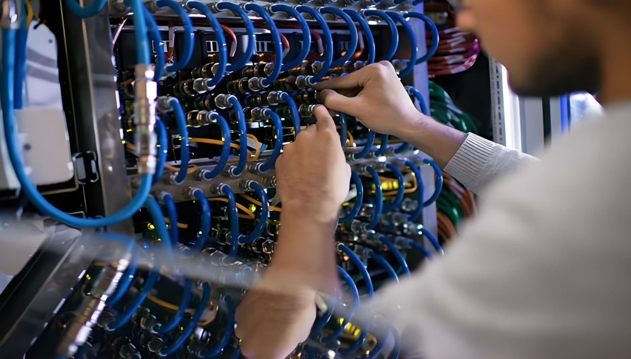
High-density patch panel deployments demand disciplined cable management — every port must be traceable in seconds, not hours
1. Why Patch Panel Management Is a Business Problem
Most network teams treat cable management as an aesthetic afterthought. That assumption collapses the first time a production link fails at 2:00 AM and the on-call engineer spends three hours tracing a cable that "should be labeled port 17" but is actually patched to port 23 in a different rack.
1.1 The Hidden Costs of Poor Management
| Impact Area | Cost of Poor Management | Benefit of Disciplined Management |
|---|---|---|
| Mean Time To Repair (MTTR) | 2–6 hours per incident tracing undocumented links | < 15 minutes with proper labeling and documentation |
| Thermal Efficiency | Blocked airflow raises inlet temps by 5–12°C | Unobstructed airflow maintains designed PUE targets |
| Change Management | Multiple technicians afraid to touch "the mess" | Confident moves, adds, and changes (MACs) without downtime |
| Audit Compliance | Fails TIA-942, ISO 55000, or SOC 2 cabling audits | Clean documentation passes audits with zero findings |
| Scalability | Rack filled with "spaghetti" at 60% capacity | Supports 95%+ port utilization with organized growth |
| Staff Turnover | Institutional knowledge lost when lead tech leaves | Self-documenting infrastructure survives personnel changes |
1.2 The Role of Patch Panels in Structured Cabling
In a properly designed structured cabling system, patch panels serve as the demarcation point between the permanent horizontal/backbone cabling and the flexible patch cord layer. This separation is intentional:
- Permanent Link: The fixed cable from the work area outlet (or cabinet) to the patch panel — tested, certified, and never moved
- Cross-Connect: Patch cords from the panel to switches, servers, or other panels — the only layer that changes during MACs
By containing all moves and changes to the patch cord layer, you protect the certified permanent infrastructure from accidental damage during routine reconfigurations.
2. Patch Panel Types & Selection Framework
Not all patch panels are created equal. Selecting the wrong type locks you into limitations that surface two years later when you upgrade to 100G or need to reconfigure for a new tenant.
2.1 Fiber Optic Patch Panels
AMPCOM's fiber offering centers on rack-mount Optical Distribution Frames (ODFs) and termination boxes with capacities from 12 to 144 fibers. These support SC, LC, and other connector types with pre-terminated pigtails, adapter panels, and splice trays. For environments that require MPO-based high‑density cassettes (e.g., 40G/100G breakout), contact AMPCOM’s technical team for custom or upcoming solutions.
| Panel Type | Fiber Count (Typical) | Connector Options | Best Application |
|---|---|---|---|
| 1U/2U Rack-Mount ODF | 12 – 48 | LC duplex, SC simplex | Enterprise MDF/IDF, 1G–100G links |
| High-Capacity ODF | 72 – 144 | LC/SC (mixed) | Backbone distribution, campus aggregation |
| Wall-Mount Enclosure | 12 – 48 | LC/SC | Edge closets, small campuses, building entries |
| Empty Rack-Mount Patch Panel (Keystone) | Up to 24 positions (fiber keystones) | LC/SC keystone | Mixed copper/fiber environments when using snap-in adapters |
2.2 Copper (Ethernet) Patch Panels
| Panel Type | Category Support | Shielding | Port Count | Termination Method |
|---|---|---|---|---|
| Feed-Through Panel | Cat5e / Cat6 / Cat6A | Unshielded / Shielded | 24 / 48 | RJ45 Couplers (no punch-down) |
| Punch-Down Panel | Cat6 / Cat6A | Unshielded / Shielded | 24 / 48 | 110/Krone punch-down tool |
| Keystone Panel (Tool-less) | Mixed (Cat6A copper, fiber, HDMI) | Per module | 24 / 48 (blank loaded) | Snap-in keystone jacks |
| Pass-Through Shielded Panel | Cat6/Cat6A | Shielded (zinc-alloy) | 24 (0.5U) | Front-accessible RJ45 couplers |
Case Study: When Feed-Through Panels Save the Day
A managed service provider in Chicago operates 200+ tenant cages in a carrier hotel. Each tenant brings their own switches with varying port densities and connector types. By standardizing on keystone patch panels with blank loadable fronts, the MSP can mix Cat6A copper, LC fiber, and MPO breakout modules in the same 1U footprint — adapting to each tenant's requirements without replacing the entire panel.
Result: MAC turnaround time dropped from 4 hours to 30 minutes per tenant change, and panel inventory was reduced by 60% (one panel type serves all use cases).
2.3 Patch Panel vs. Switch: Know the Difference
A common confusion in procurement: "Can't we just use a top-of-rack switch as a patch panel?" Technically yes, but with critical trade-offs:
- Switches are active devices: They consume power, generate heat, and fail at a higher rate than passive panels
- Port density mismatch: A 48-port switch forces you to use all 48 ports or waste capacity; a patch panel lets you populate ports as needed
- Budget reality: A 48-port Cat6A patch panel costs a fraction of an equivalent switch, freeing budget for active electronics where it matters
- Operational separation: Network teams manage switches; cabling teams manage panels — mixing them creates change-control conflicts

Proper horizontal and vertical cable managers transform a chaotic rack into a maintainable, scalable infrastructure
3. Rack Design & Cable Routing Principles
Great cable management starts before a single cable is pulled. Your rack layout determines whether your rack organization will scale gracefully or collapse under its own weight.
3.1 The 1U Planning Rule
Rack Unit Allocation Framework
Bottom 2U: PDUs (power distribution units) — one left, one right for redundancy
Next 4–6U: High-density patch panels (fiber first, then copper) — keep all panels in a contiguous block
Above panels: 1U horizontal cable manager immediately above each panel row
Switch rows: 1U horizontal cable manager above each switch row (top-exit patching)
Top 4–6U: Vertical cable managers, spares, and future-growth reserve
Golden rule: For every 1U of active equipment, allocate 1U of cable management
3.2 Cable Pathway Design
| Routing Method | Best For | Bend Radius Rule | Capacity Planning |
|---|---|---|---|
| Vertical Managers (Side) | Inter-rack patches, long patch cords | ≥ 4× cable diameter (copper) ≥ 10× cable diameter (fiber) |
Fill ≤ 50% of cross-section for future growth |
| Horizontal Managers (Front) | Short patches from panel to switch | Same as above; use finger ducts, not rings | Plan for 1.5× the port count in patch cords |
| Underfloor / Overhead Trays | Permanent horizontal/backbone cables | ≥ 25mm (fiber), ≥ 15mm (copper) | Reserve 30% empty space for moves |
3.3 Service Loops: The Forgotten Best Practice
A service loop (also called a maintenance loop) is 30–50cm of extra cable coiled at each termination point. It serves three purposes:
- Re-termination margin: If a connector fails, you have spare jacket to re-terminate without pulling a new cable
- Equipment slides: When you slide a server or switch out for service, the service loop prevents tension on the fixed connection
- Label protection: Coiling the loop keeps labels visible and accessible, not buried behind equipment
4. Proven Management Techniques (Step-by-Step)
The following techniques are field-validated across hundreds of data center deployments. Skip any step, and you'll pay for it during the first major reconfiguration.
4.1 Labeling Systems That Survive
A label that falls off after six months or becomes unreadable in a cold aisle is worse than no label at all. Here’s a hierarchical labeling framework that works across multi‑vendor installations:
Recommended Label Coding Practice
Cabinet ID: DC1-B-07 (Data Center 1 – Zone B – Cabinet 07)
Patch Panel ID: PP-DC1-B-07-01 (PP = Patch Panel, location, sequence)
Port Label (on panel): 01–48 (matches port mapping database)
Cable Label (both ends): C-DC1-B-07-01-23↔DC1-C-12-02-11 (Origin ↔ Destination)
Color coding: Production = white, Backup = yellow, Cross-connect = blue, Management = green
Label specs: Heat-shrink or wrapped polyester, 12mm width, QR code optional for scan-to-database
4.2 The Right Way to Bundle Cables
| Bundling Method | When to Use | Pros | Cons |
|---|---|---|---|
| Velcro Hook-and-Loop | All patch cord bundling | Reusable, no crush damage, adjustable | Slightly higher cost than zip ties |
| Plastic Zip Ties | Never (except temporary) | Cheap, readily available | Crush fibers, permanent, sharp edges |
| Lacing Bars | High-density MPO trunks | Neat, professional, no protrusions | Slower installation, requires skill |
| Cable Trays/Fingers | Horizontal managers | Individual cable routing, no bundling needed | Lower density than bundled approaches |
4.3 Length Selection: The 90% Rule
One of the most common mistakes in patch panel wiring is using cables that are "long enough to be safe" — which typically means 2–3× longer than necessary.
Cable Length Planning Checklist
- Measure the actual path: Vertical manager → horizontal manager → port — not straight-line distance
- Add service loop: +30cm at each end for maintenance margin
- Target 90% fill: Cable should reach with slight slack, not draping or taut
- Standardize lengths: Use 0.5m, 1m, 2m, 3m standardized lengths — not custom cuts
- Avoid excess: Cables longer than 3m in a single rack should be re-routed through managers
4.4 EMI and Shielding Considerations
In high-density environments with 400G+ channels, electromagnetic interference (EMI) can degrade signal integrity even on fiber links (through micro-bending induced by vibration).
- Shielded patch panels: Use S/FTP (shielded) panels in environments with high EMI — near power distribution, UPS systems, or radio equipment
- Proper grounding: Shielded panels must be bonded to rack ground with ≤ 2.5mm² grounding wire; verify continuity with a multimeter
- Fiber advantage: Fiber optic patch panels are inherently immune to EMI — choose fiber for high-EMI zones even if the distance is short
- Separation distance: Maintain ≥ 30cm separation between copper data cables and AC power cables; cross at 90° when crossing is unavoidable
Case Study: Large Enterprise Campus Standardization
A major educational institution standardized their campus-wide network infrastructure using AMPCOM patch panels across multiple buildings. Each building MDF (Main Distribution Frame) adopted a consistent labeling scheme: PP-[Building]-[Floor]-[Closet]-[Sequence].
The challenge: High-density user areas required frequent MACs (Moves, Adds, Changes), and the previous unlabeled panels led to hours of troubleshooting per incident.
The solution: Port mapping database linked to label codes, color-coded cables (user = blue, admin = white, research = green), and 1U horizontal managers above every panel.
Result: MAC turnaround dropped to under 20 minutes on average. The network operations center (NOC) reported a significant reduction in cabling-related tickets in the months following the standardization.
5. AMPCOM Solutions for Every Environment
AMPCOM's patch panel and cable management portfolio spans from compact edge closets to high‑density data centers. All products listed below are available on the official AMPCOM Patch Panels product page. The panels are designed with industry standards in mind; for specific compliance with TIA‑568.2‑D, ISO/IEC 11801, or IEC 60603‑7, please refer to the individual product specification sheets.
5.1 Data Center High‑Density Copper Solutions
AMPCOM High‑Density Copper Patch Panels
1U 48‑Port Unshielded 180° Punch‑Down Keystone Patch Panel — Delivers 48 ports in a 1U footprint with rear‑facing 180° punch‑down keystone jacks. Integrated cable management rings keep horizontal cabling structured, and the tool‑less keystone design speeds up deployment and MAC work.
1U 48‑Port Unshielded Tool‑Less Keystone Patch Panel — Same 48‑port high density, but all keystone jacks snap in without any punch‑down tool. Ideal for rapid installation in high‑turnover colocation cages and enterprise data centers.
0.5U 24‑Port Modular Unshielded Patch Panel — Half‑rack‑width design saves vertical space while offering full keystone flexibility. A reinforced copper grounding wire and a removable front bezel simplify maintenance. Populate with Cat6/Cat6A copper, LC fiber, or HDMI keystones as needed.
Pair these panels with AMPCOM’s Cat6 unshielded or shielded keystone jacks (rated for 250 MHz and PoE+ IEEE 802.3at) to build a high‑speed copper channel that scales from 1 Gbps to 10 Gbps.
5.2 Enterprise Copper Solutions
| AMPCOM Product | Ports | Termination Style | Key Feature |
|---|---|---|---|
| 1U 48‑Port Unshielded 180° Punch‑Down Panel | 48 | 180° Punch‑Down Keystone | Rear cable management ring; supports Cat6/Cat6A |
| 1U 48‑Port Unshielded Tool‑Less Keystone Panel | 48 | Tool‑Less Keystone | Fast snap‑in modules; mixed media capable |
| 1U 24‑Port Unshielded Pass‑Through Panel | 24 | RJ45 Coupler (Feed‑Through) | Front‑accessible ports for frequent patching changes |
| 1U 24‑Port Front‑Removable Keystone Panel | 24 | Keystone (Front‑Removable) | Tool‑less front bezel removal for easy module swaps |
| CAT6 Premium Series Punch‑Down Panel | 24/48 | 110 Punch‑Down | 15μ gold‑plated contacts; T568A/B color‑coded |
5.3 Cable Management Accessories
AMPCOM’s cable management ecosystem ensures every patch cord has a dedicated, bend‑radius‑compliant pathway:
- 1U Horizontal Cable Manager (with Cover) — Finger duct with 45×45 mm spacing; front‑removable cover; directs patch cords neatly between panels and switches while preventing airflow blockage.
- 0U Vertical Cable Manager — Snaps onto rack side channels for vertical patching; handles inter‑rack and long patch cords with proper bend radius control.
- Hook‑and‑Loop (Velcro) Cable Ties — Reusable, non‑crush fasteners in black or assorted colors; recommended over zip ties for all structured cabling bundles.
- Integrated Cable Management Rings — Many AMPCOM patch panels include built‑in rear rings, allowing installers to secure cables directly at the panel for strain relief and a clean finish.
5.4 Voice & Telecom Solutions
AMPCOM Voice Patch Panels
AMPCOM 100‑Pair 110‑Type RJ11 Patch Panel — Cold‑rolled steel construction, 19‑inch rack‑mountable. Equipped with 110‑type IDC punch‑down blocks and T568A/B color‑coded labeling, it provides a centralized termination point for telephony trunk lines and enterprise voice networks.
AMPCOM Modular RJ11 Voice Panel — Available in 25‑ and 50‑port configurations, also housed in SPCC steel. Designed for professional voice cabling systems that require modular flexibility and easy re‑patching.
5.5 Fiber Optic Connectivity (ODF)
AMPCOM Optical Distribution Frames
AMPCOM offers a wide range of optical fiber termination boxes (ODF) and accessories for splicing, termination, and patching. Configurations from 12 to 144 fibers are available, supporting SC, LC, and other adapter types. Pre‑terminated pigtails, adapter panels, and splice trays enable fast deployment in enterprise backbones and data center fiber links.
For detailed port counts, connector types, and selection guidance, visit the AMPCOM Fiber Optic Solutions page or contact the technical support team.
AMPCOM patch panels and cable management accessories — designed for rapid deployment and orderly scaling in any environment
6. Key Questions & Answers
Frequently Asked Questions About Patch Panel Cable Management
Related Articles
- How AI Infrastructure Is Reshaping Data Center Cabling Requirements — Understanding the unique demands of AI workloads on network infrastructure
- Structured Cabling for AI Data Centers: What Is Changing — Key differences between traditional and AI-optimized cabling designs
- MPO Fiber Solutions for Data Center and High-Density Cabling — Selecting the right MPO configuration for your deployment
- How to Choose the Right Fiber Type: Singlemode vs Multimode — OM3/OM4 vs OS2: matching fiber type to link speed and distance

AMPCOM Technical Team
Industry experts with 17+ years in enterprise network infrastructure and structured cabling systems
Ready to upgrade your patch panel infrastructure?
AMPCOM provides free rack layout consulting, custom labeling schemes, and rapid-delivery patch panels for data centers and enterprise networks worldwide.
Get Free Expert Consultation

