
Data Center Cabling: MDF vs IDF vs EoR vs ToR Architecture Explained
Published:Executive Summary: Data center cabling runs on acronyms — and four of them define how your entire physical-layer topology is structured. MDF (Main Distribution Frame) is where the outside world meets your network. IDF (Intermediate Distribution Frame) is how you distribute connectivity across floors and zones without violating TIA cabling distance limits. EoR (End of Row) and ToR (Top of Rack) determine whether you centralize your access-layer switches or push one into every cabinet.
Get any one of these decisions wrong, and you do not just waste cable — you build a topology that locks in port underutilization, inflated cooling cost, or a failure domain too wide to tolerate. This guide maps all four acronyms against the architectural decisions that shape your data center: where equipment lives, what cable it uses, how far it can reach, and what breaks when something fails.
Quick Navigation
- 1 MDF: The Building's Network Nerve Center
- 2 IDF: The Floor-Level Distribution Layer
- 3 EoR (End of Row): Centralized Switch Architecture
- 4 ToR (Top of Rack): Distributed Switch Architecture
- 5 MDF IDF: Hierarchy, Distance, and Cable Selection
- 6 EoR vs ToR vs MoR: Complete Comparison Matrix
- 7 The Full Architecture Chain: MDF IDF + EoR/ToR
- 8 Cable Types, Standards, and Distance Limits
- 9 Common Mistakes and Real-World Pitfalls
- 10 Selection Framework by Deployment Scale
- KQ Key Questions & Answers

Cross-sectional diagram of a multi-floor data center showing the MDF room on the ground floor (Credit: AMPCOM)
1. MDF: The Building's Network Nerve Center
1.1 What an MDF Actually Is
The Main Distribution Frame (MDF) is the primary telecommunications room in any building — the point where external carrier circuits (ISP fiber, MPLS circuits, dark fiber, POTS lines) physically enter the facility and terminate onto the organization's core network equipment. In a data center context, the MDF is often synonymous with the meet-me room (MMR) or main cross-connect room. It houses the core routers, core switches, firewalls, WAN edge devices, and the first tier of fiber optic patch panels that organize incoming and outgoing circuits.
The MDF is not optional. Every structured cabling system defined by TIA-568 and ISO/IEC 11801 starts with a main cross-connect — and that cross-connect lives in the MDF. Without an MDF, you have no demarcation point, no centralized patching field, and no single location where a technician can isolate whether a connectivity problem is inside your network or on the carrier side.
1.2 Physical Requirements for an MDF
An MDF room is not just a closet with a switch. It requires:
- Physical security: Access-controlled entry (badge, biometric, or key), video surveillance, and a tamper log. The MDF is the single most sensitive room in the building's network infrastructure — if an unauthorized person gains access here, they have access to every circuit entering and leaving the facility.
- Environmental control: Dedicated HVAC or CRAC units maintaining 18–27°C (64–80°F per ASHRAE TC 9.9 recommended range) with humidity between 40–60% RH. Core routers and chassis switches generate significant heat; an MDF without adequate cooling will thermal-throttle during peak traffic.
- Power resilience: Dual power feeds from separate PDUs, backed by UPS with a minimum 15-minute runtime at full load, plus a generator transfer switch. The MDF is the first room that goes dark in a power failure — and the last room that should recover.
- Cable entry and pathway: Conduit sleeves or cable tray penetrations for carrier fiber entry, backbone cabling pathways to IDF rooms, and overhead ladder rack for intra-room patching.
- Grounding: A telecommunications grounding busbar (TGB) bonded to the building's primary grounding electrode system per TIA-607-C. Every rack, ladder rack, and cable shield in the MDF ties to this busbar.
1.3 Equipment Typically Found in an MDF
| Equipment Type | Role in the MDF | Typical Port Count |
|---|---|---|
| Core routers | WAN edge — terminate carrier circuits, run BGP/OSPF | 8–48 x 100GE/400GE |
| Core switches (chassis or fixed) | Aggregate all IDF backbone links; L3 distribution | 48–288 x 25GE/100GE |
| Firewalls / NGFW | Perimeter security, VPN termination, IPS/IDS | 4–48 x 10GE/100GE |
| Fiber patch panels (ODF) | Organize, protect, and label fiber backbone terminations | 48–288 ports per panel |
| Copper patch panels | Terminate Cat6a/Cat7 horizontal runs (if any) | 24–48 ports per 1U panel |
| UPS / PDU | Power conditioning and battery backup | N/A — power infrastructure |
2. IDF: The Floor-Level Distribution Layer
2.1 What an IDF Is and Why It Exists
An Intermediate Distribution Frame (IDF) is a secondary telecommunications room that connects back to the MDF via backbone cabling and serves a specific zone — typically one floor of a multi-story building, one wing of a large single-story facility, or one pod within a hyperscale data center. The IDF exists for one reason: distance. Per TIA-568 structured cabling standards, the maximum horizontal copper channel length is 100 meters (328 feet) from the patch panel in the telecommunications room to the work-area outlet. On a floor that spans 200 meters end-to-end, a single MDF on one side cannot serve outlets on the opposite side — the IDF bridges that gap.
2.2 IDF Equipment and Density
An IDF room is simpler than an MDF. It typically contains:
- Distribution (access-layer) switches: Fixed-configuration 24/48-port switches providing 1GE, 10GE, or 25GE access ports to servers and endpoints. These are the workhorses of the IDF — they consume the majority of rack space and power.
- Fiber patch panels: Terminate the backbone fiber runs from the MDF and cross-connect to IDF switch uplink ports. In modern deployments, MPO-to-LC cassettes or pre-terminated MPO trunk assemblies simplify this patching field.
- Copper patch panels: Terminate horizontal copper runs to individual server cabinets or work-area outlets within the IDF's coverage zone.
- Cable management: Horizontal and vertical managers to route patch cords from the fixed cabling (the back of the panel) to the switch ports (the front of the panel). IDF rooms with poor cable management are the single largest source of on-site troubleshooting delays.
- UPS (optional but recommended): A smaller UPS dedicated to the IDF switch stack. In facilities where the MDF UPS covers the entire building, the IDF may still have a local UPS for graceful shutdown sequencing.
2.3 When an IDF Is Not Needed
Not every deployment requires IDFs. A single-floor data center under roughly 10,000 sq ft with all server cabinets within 100 meters of the MDF can use a collapsed MDF architecture — all horizontal cabling terminates directly in the MDF, and there are no intermediate distribution points. This reduces equipment count, simplifies patching, and eliminates the cost of additional climate-controlled rooms. The trade-off is that every horizontal cable is longer, every patch cord route is more congested, and the MDF must be sized to accommodate the combined patching field of what would otherwise be distributed across multiple IDFs.

Data center eor vs mor rack layout comparison (Credit: AMPCOM)
3. EoR (End of Row): Centralized Switch Architecture
3.1 How End of Row Cabling Works
In an End of Row (EoR) architecture, access-layer switches are not placed inside individual server cabinets. Instead, one or two dedicated network cabinets are positioned at the end of each row of server racks. Every server in the row connects back to these centralized switches via structured cabling — typically copper (Cat6a) for 1G/10GBASE-T links or multimode fiber (OM4) for 10G/25G SFP+ links. This is the most traditional data center cabling topology: servers in cabinets, switches at the row end, and a fiber backbone connecting the row-end switches up to the aggregation or core layer.
3.2 EoR Cable Count and Management
The defining characteristic of EoR is cable volume per server cabinet. Each rack typically runs 20–40 cables (copper, fiber, or DAC) from the server NICs to a patch panel inside the same cabinet, then through overhead or under-floor cable trays to the network cabinet at the row's end. For a row of 20 cabinets at 30 cables each, that is 600 cables converging on one or two network cabinets. This density requires disciplined cable management — color-coded patch cords, proper labeling on both ends, horizontal and vertical managers at every cabinet, and enough overhead tray capacity to avoid compression that degrades Cat6a alien crosstalk performance.
3.3 EoR Switch Selection
EoR deployments typically use chassis-based modular switches (Cisco Catalyst 9400/9600, Arista 7500R, Juniper EX9200, Huawei CE12800) rather than fixed-configuration 1U boxes. A chassis switch offers:
- Line card flexibility: Mix 48-port 10GE, 36-port 40GE, and 36-port 100GE line cards in a single chassis to match the exact port mix the row requires.
- Hardware redundancy: Dual supervisor engines, dual power supplies, and N+1 fan trays — a single component failure does not take down the row. In ToR, a switch failure takes down one cabinet. In EoR, a switch failure takes down every cabinet in the row, which is why the switch itself must be redundant.
- Port density efficiency: A single 14-slot chassis can serve 300+ server ports. Fixed-configuration switches to cover the same port count would require 7+ individual devices, each with its own management plane.
- Investment protection: When the row needs to upgrade from 10GE to 25GE server access, you swap line cards — not the entire switch fleet. A chassis purchased in 2026 can still be the row switch in 2036 with upgraded interface modules.
3.4 EoR Advantages and Disadvantages
| Advantage | Disadvantage |
|---|---|
| High port utilization — chassis switch ports are pooled across the entire row, eliminating the "stranded port" problem of ToR | Long cable runs — the farthest cabinet in a 30-meter row runs 30 meters of cable plus patch cords, approaching copper distance limits at higher speeds |
| Fewer switches to manage — 1–2 chassis per row vs. 20+ ToR switches | Large failure domain — a chassis backplane failure takes the entire row offline |
| Lower aggregate power consumption — fewer total switching ASICs and fewer power supplies | Cable congestion at row ends — 600+ cables converging on two cabinets creates a physical bottleneck that complicates MAC work |
| Simpler network topology — fewer L2/L3 hops between servers in the same row | Upgrade coordination — upgrading a chassis line card often requires a maintenance window for the entire row |
4. ToR (Top of Rack): Distributed Switch Architecture
4.1 How Top of Rack Cabling Works
In a Top of Rack (ToR) architecture, every server cabinet gets its own access-layer switch — typically a 1U or 2U fixed-configuration switch mounted at the top of the cabinet (or occasionally in the middle for weight distribution). Servers inside that cabinet connect to the ToR switch via short patch cords — under 3 meters for copper, under 5 meters for DAC or fiber. The ToR switch then connects upstream to aggregation switches via fiber uplinks (typically 40GE QSFP+, 100GE QSFP28, or 400GE QSFP-DD). There are no long horizontal cable runs between cabinets — the only cables leaving the cabinet are the fiber uplinks.
4.2 The Port Utilization Problem
ToR's biggest known weakness is port underutilization. A standard ToR switch provides 48 x 25GE SFP28 downlink ports plus 6–8 x 100GE QSFP28 uplink ports. But a single cabinet — constrained by power delivery (typically 5–12 kW per cabinet) and physical space (42U) — rarely holds 48 servers. A typical density is 20–30 servers per cabinet, leaving 18–28 switch ports unused. Multiply that across 200 cabinets and you have thousands of purchased but unproductive switch ports — a capital inefficiency that EoR, by pooling switch ports at the row level, avoids.
The industry mitigates this through two strategies:
- Cross-connect between adjacent cabinets: A 48-port ToR switch serves its own cabinet (24 ports) and the adjacent cabinet (24 ports) via short cross-connect cables through a shared cable management slot. This doubles port utilization but introduces a dependency between two cabinets that undermines ToR's fault-isolation advantage.
- Higher-density server packaging: Multi-node chassis (2U4N) pack four independent server nodes into 2U of rack space, pushing cabinet density closer to the switch port count. This is common in hyperscale deployments where server and switch density are designed together from the chassis level up.
4.3 ToR Advantages and Disadvantages
| Advantage | Disadvantage |
|---|---|
| Minimal inter-rack cabling — only fiber uplinks leave the cabinet, dramatically simplifying cable trays and reducing copper cable cost | High switch count — 200 cabinets = 200+ switches to manage, configure, monitor, and firmware-update |
| Per-cabinet fault isolation — a switch failure affects one cabinet, not an entire row | Port underutilization — 30–60% of purchased switch ports may sit idle depending on server density per cabinet |
| Phased deployment — you can populate one cabinet at a time; no need to install row-level infrastructure upfront | Higher aggregate power — more individual switch PSUs and ASICs consume more total watts than a consolidated chassis approach |
| Easy upgrades — swap the ToR switch in one cabinet without touching any other cabinet in the row | Management overhead — ZTP (Zero Touch Provisioning) and automation tools are mandatory at scale; manual switch-by-switch config is unsustainable |
| Lower latency — server-to-switch hop is under 3 meters of copper, contributing nanosecond-level port-to-port latency within the rack | More fiber uplink ports consumed at the aggregation layer — each ToR switch needs its own uplink, multiplying the aggregation switch port count |
5. MDF ↔ IDF: Hierarchy, Distance, and Cable Selection
5.1 The MDF-to-IDF Backbone
The connection between MDF and IDF is called the building backbone (or vertical backbone in multi-story buildings) in TIA-568 nomenclature. This is the highest-bandwidth, lowest-latency link in the building's structured cabling system — everything that happens in every IDF room must traverse this backbone to reach the core network, the internet, or another IDF zone.
5.2 Backbone Cable Selection by Distance and Speed
| Backbone Distance | Recommended Cable Type | Max Speed Supported | Connector Type |
|---|---|---|---|
| 0–100 meters | Cat6a (23 AWG) shielded | 10GBASE-T (100m); NBASE-T 2.5/5G | RJ45 |
| 0–100 meters | OM4 multimode fiber | 100GBASE-SR4 (100m); 400GBASE-SR8 (100m) | MPO-12/MPO-16 or LC duplex |
| 100–400 meters | OM4 multimode fiber | 10GBASE-SR (400m); 40GBASE-SR4 (150m) | MPO-12 or LC duplex |
| 400 meters–10 km | OS2 singlemode fiber (G.652.D) | 10GBASE-LR (10km); 100GBASE-LR4 (10km); 400GBASE-FR4 (2km) | LC/UPC duplex |
| 10 km–80+ km | OS2 singlemode + DWDM | 100G DWDM; 400G ZR/ZR+ | LC/UPC or SC/APC |
5.3 IDF Coverage Radius
Each IDF serves a coverage zone — the set of server cabinets, work-area outlets, or equipment locations that fall within 90 meters of horizontal cable from that IDF's patch panels. In a rectangular data center floor, a single centrally-located IDF can cover a circle of approximately 180 meters in diameter. Beyond that, you need a second IDF. The limiting factor is almost always copper horizontal cabling — fiber horizontal runs (used for 10G/25G/100G server connections) have usable distances far exceeding 100 meters, but most data centers still run a mix of copper and fiber to each cabinet for management networks, out-of-band access, and legacy equipment.

High-density data center operations — overhead tray routing visible above the racking infrastructure, showing the interconnected nature of steel and cabling planning (Credit: AMPCOM)
6. EoR vs ToR vs MoR: Complete Comparison Matrix
| Dimension | EoR (End of Row) | MoR (Middle of Row) | ToR (Top of Rack) |
|---|---|---|---|
| Switch location | Network cabinet at row end | Network cabinet at row center | 1U/2U switch in every server cabinet |
| Switch type | Chassis-based modular (Cisco 9400, Arista 7500R) | Chassis-based or high-density fixed | Fixed-configuration 1U/2U (Cisco Nexus 9300, Arista 7050X) |
| Switch count per row (20 cabinets) | 1–2 chassis switches | 1–2 chassis switches | 20–40 fixed switches (1–2 per cabinet) |
| Server-to-switch cable length | 3–30 meters (depending on cabinet position in row) | 3–15 meters (half the row length from center) | 0.5–3 meters (within same cabinet) |
| Cables per cabinet (approximate) | 20–40 cables leaving the cabinet | 20–40 cables leaving the cabinet | In-cabinet only; 2–8 fiber uplinks leaving |
| Typical server cable type | Cat6a copper or OM4 fiber (longer runs) | Cat6a copper or OM4 fiber | Cat6a copper, DAC, or AOC (short runs) |
| Uplink cabling | Fiber from row-end to aggregation (MDF) | Fiber from row-center to aggregation (MDF) | Fiber from each ToR switch to aggregation |
| Port utilization | High — ports pooled across entire row | High — same pooling as EoR | Low to moderate — 30–60% typical without cross-connect |
| Fault domain | Entire row (mitigated by redundant chassis) | Entire row | Single cabinet |
| Management complexity | Low — 1–2 devices to manage per row | Low — same as EoR | High — 20+ devices per row; automation essential |
| Scalability / expansion | Add line cards to chassis or add new chassis | Same as EoR | Add cabinets — each self-contained |
| Power consumption | Lower aggregate — fewer PSUs, higher efficiency per port | Similar to EoR | Higher aggregate — each 1U switch adds 100–300W |
| Cable management effort | High — 600+ cables converging at row-end cabinets | Moderate — cables converge at center, shorter max runs | Low — cables contained within each cabinet |
| Common deployment environments | Colocation, enterprise data centers, smaller server rooms | Mid-size data centers optimizing cable cost | Hyperscale, cloud, AI/ML clusters, any high-density or phased-build facility |
7. The Full Architecture Chain: MDF → IDF → EoR/ToR
7.1 How the Acronyms Stack Together
These four acronyms are not independent choices — they describe a layered topology. In a fully built-out multi-floor data center, the architecture chain looks like this:
Layer 1: External Connectivity → MDF
Carrier fiber enters the building at the MDF meet-me room. Core routers terminate BGP peering and MPLS circuits. Core switches aggregate all building backbone links. This is Layer 1 of the hierarchy — the single point where outside meets inside.
Layer 2: MDF → IDF (Building Backbone)
Fiber backbone cables run from the MDF core switches to distribution switches in each IDF room — typically one IDF per floor or per 180-meter coverage zone. The backbone uses OS2 singlemode for long runs or OM4 multimode for intra-building distances under 400 meters. MPO trunk cables are increasingly common for 40G/100G parallel optic backbone links.
Layer 3: IDF → Server Cabinets (Horizontal Distribution)
This is where the EoR/MoR/ToR decision lives. Within each IDF's coverage zone:
- If EoR or MoR: The IDF room itself acts as the network cabinet. Horizontal cabling (copper Cat6a or OM4 fiber) runs from the IDF patch panels to each server cabinet in the zone. Servers connect to cabinet-level patch panels, which connect back to the IDF switches.
- If ToR: The IDF room hosts aggregation switches only. Each server cabinet in the zone has its own ToR switch connected via fiber uplink to the IDF aggregation switch. No long horizontal server cables exist — only fiber uplinks between cabinets and the IDF.
7.2 Real Example: 3-Floor, 600-Cabinet Data Center
| Floor | MDF/IDF | Architecture Choice | Equipment |
|---|---|---|---|
| Ground Floor | MDF (meet-me room) | N/A — core layer | 2 x core routers (100GE), 2 x core chassis switches (288 x 100GE), ODF panels |
| Floor 1 | IDF-1 (west wing) | ToR | 2 x aggregation switches (64 x 100GE), 40 x ToR cabinets each with 1 x 48-port 25GE switch |
| Floor 1 | IDF-2 (east wing) | ToR | Same as IDF-1 (mirror deployment) |
| Floor 2 | IDF-3 (full floor) | MoR | 2 x chassis switches in center cabinet, 100 x server cabinets with patch panels and Cat6a horizontal runs |
This hybrid approach — ToR on floor 1 for the dense compute cluster, MoR on floor 2 for the lower-density storage tier — is common in real deployments. The MDF/IDF backbone is the same; only the horizontal architecture within each IDF zone differs.
8. Cable Types, Standards, and Distance Limits
8.1 Key Standards Governing These Architectures
| Standard | What It Governs | Key Limit Relevant to MDF/IDF/EoR/ToR |
|---|---|---|
| ANSI/TIA-568.0-D / 568.1-D | Generic telecommunications cabling — topology, architecture, channel definitions | Maximum horizontal copper channel: 100 meters (90m horizontal + 10m patch cords) |
| ANSI/TIA-568.3-D | Optical fiber cabling components and testing | Fiber backbone distances defined by application (Ethernet standard) not by TIA cable spec |
| ANSI/TIA-942-C | Data center telecommunications infrastructure — rated tiers (Rated 1–4) | Specifies MDF, IDF (HDA, ZDA), and EoR/ToR (EDA) topology for each reliability tier |
| ISO/IEC 11801-5 | Data center cabling (international equivalent of TIA-942) | Same topology structure: MDC (main), IDC (intermediate), ZDC (zone), EDC (equipment) |
| IEEE 802.3 (various clauses) | Ethernet PHY specifications — distance limits per speed | 10GBASE-T: 100m on Cat6a; 100GBASE-SR4: 100m on OM4; 100GBASE-LR4: 10km on OS2 |
| ANSI/BICSI 002-2024 | Data center design and implementation best practices | Detailed guidance on MDF/IDF room sizing, pathways, thermal management, and structured cabling layout |
8.2 Horizontal vs. Backbone Cable Selection
A recurring mistake in data center cabling design is treating all cable runs the same. The MDF-to-IDF backbone and the IDF-to-server horizontal runs have fundamentally different requirements:
- Backbone (MDF ↔ IDF): Prioritize bandwidth headroom and future-proofing. Install OS2 singlemode even if you are only running 10G today — the incremental cost of singlemode fiber over multimode on a 12-strand trunk is approximately 10–15%, but the speed ceiling jumps from 100G to 400G+ without recabling. Pre-terminated MPO trunk cables in 12F or 24F configurations simplify backbone deployment dramatically.
- Horizontal (IDF ↔ Server, EoR/MoR): Match the cable to the server NIC speed and distance. Cat6a for 1G/10GBASE-T under 100 meters. OM4 multimode for 25G SFP28 server connections under 100 meters. The cable type should be a decision, not a default — specifying OM4 fiber for a server that only has 1GBASE-T copper NICs wastes budget with zero performance gain.
- Horizontal (within cabinet, ToR): DAC (Direct Attach Copper) cables for 10G/25G connections under 5 meters — they are cheaper than optical transceivers, consume no power at the connector, and add near-zero latency. AOC (Active Optical Cables) for 25G/100G connections where weight, bend radius, or EMI immunity justifies the cost premium over DAC.
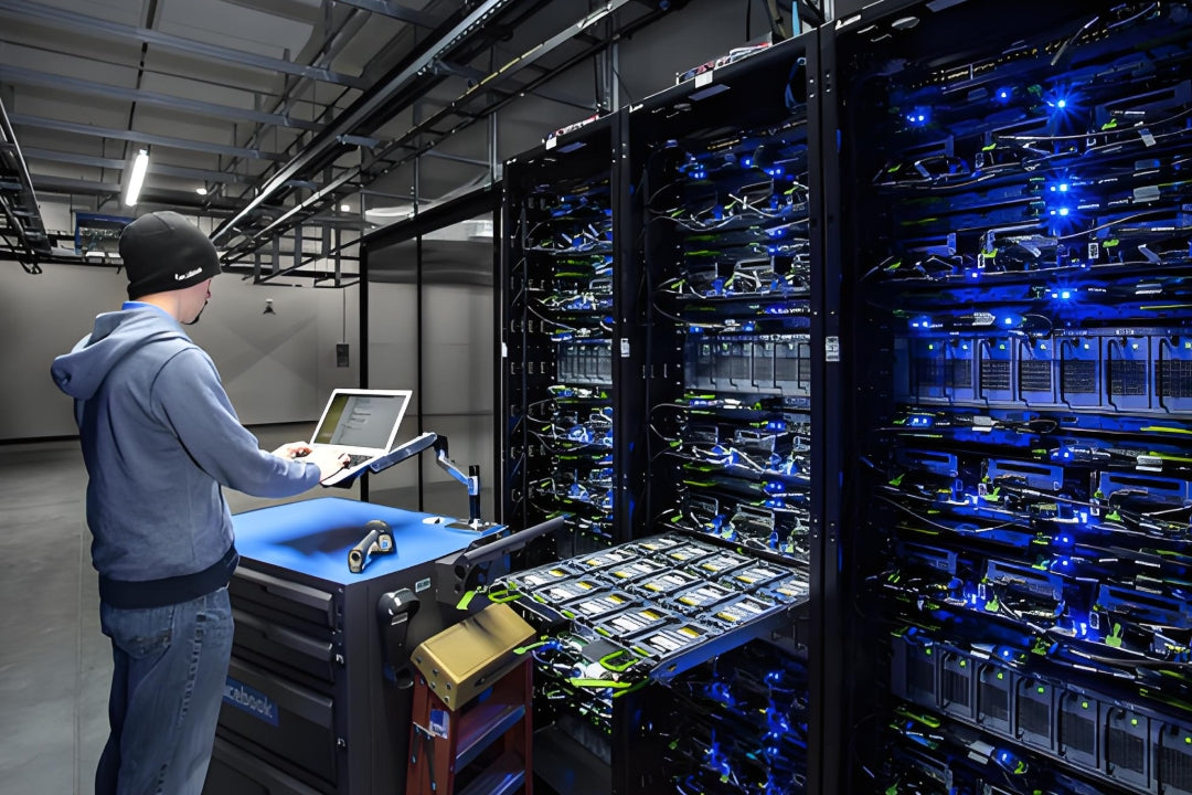
High-density fiber patching in a modern data center — overhead tray routing and bend radius management are finalized during the steel erection phase (Credit: AMPCOM)
9. Common Mistakes and Real-World Pitfalls
Top 6 Data Center Cabling Architecture Mistakes
Mistake #1: Designing a single MDF with no IDFs for a building that spans more than 100 meters.
The TIA-568 100-meter copper channel limit is non-negotiable. If your building is 150 meters end-to-end, a single MDF violates the standard the moment the first server on the far side is patched. The fix is not "use fiber for those long runs" unless you are prepared to specify fiber NICs for every server at the far end. The proper fix is an IDF at the 90-meter mark. Budget for the IDF room during architectural design, not during cabling deployment when the violation is already baked into the floor plan.
Mistake #2: Deploying ToR without a management automation strategy.
A 200-cabinet ToR deployment means 200 individual switches — 200 management IPs, 200 configs, 200 firmware versions, and 200 devices to audit. Without ZTP (Zero Touch Provisioning), Ansible/Puppet automation, and a centralized monitoring platform (SNMP + streaming telemetry), this becomes unmanageable within 6 months. The labor cost of manual switch-by-switch administration often exceeds the hardware savings that ToR's simplified cabling was supposed to deliver.
Mistake #3: Running EoR with non-redundant switches.
In ToR, a switch failure takes down one cabinet. In EoR, a switch failure takes down the row. If you deploy EoR with a single chassis switch and a single supervisor, you have created a single point of failure for 20–40 cabinets. At minimum, EoR chassis switches must have dual supervisors, dual power supplies, and ideally a second chassis in the opposite-end network cabinet with LACP multi-chassis link aggregation (MLAG or vPC) to the servers.
Mistake #4: Mixing backbone and horizontal cable selections without a speed roadmap.
A backbone cable installed today will carry traffic for 10–15 years. Installing OM3 multimode for a backbone that currently runs 10G but will need 100G in 4 years is a false economy — OM3 supports 100GBASE-SR4 only to 100 meters, which may not reach between MDF and IDFs. The $200 you save today on OM3 vs. OS2 singlemode will cost $15,000+ in labor and downtime to recable the backbone in 4 years.
Mistake #5: Ignoring the PUE and thermal impact of architecture choice.
A 200-cabinet ToR deployment adds approximately 20–60 kW of additional switch power load (100–300W per 1U switch) compared to a consolidated EoR chassis design. This directly increases PUE because every watt consumed by switching ASICs becomes heat that the cooling system must remove. In a facility with a PUE of 1.4, the 40 kW of switch load becomes 56 kW at the utility meter. Over a 5-year equipment lifecycle, that is roughly $50,000–150,000 in additional electricity cost at $0.10/kWh — often more than the hardware cost difference between ToR and EoR.
Mistake #6: Failing to document the MDF/IDF cross-connect field.
The MDF fiber patching field — the cross-connect between carrier circuits, core switch ports, and backbone fiber strands — is the single most critical documentation point in the entire building. When a carrier circuit goes down, the technician who arrives at 3 AM needs to trace the fiber path from the street entrance panel, through the ODF, to the core router port, in under 5 minutes. Without labeled patch panels, port maps, and a digital record (DCIM or spreadsheet), that 5-minute trace becomes a 3-hour outage. The documentation cost is near zero; the outage cost is measured in SLA penalties and lost revenue.
10. Selection Framework by Deployment Scale
10.1 Small Data Center / Server Room (1–20 cabinets, single floor)
Architecture: MDF only + EoR. No IDFs needed — all cabinets are within 100 meters of the MDF. An EoR design with a single chassis switch (or two for redundancy) in the MDF serves all cabinets. Horizontal Cat6a copper cables run directly from the MDF patch panels to each server cabinet. This keeps the switch count low (1–2), maximizes port utilization, and eliminates the cost of climate-controlled IDF rooms. Fiber backbone is only needed between the MDF core and upstream WAN routers.
10.2 Medium Enterprise Data Center (20–100 cabinets, single floor)
Architecture: MDF + 1–2 IDFs + MoR or ToR. If the floor spans more than 100 meters from end to end, deploy one centrally-located IDF (MoR topology) or two IDFs at opposite ends. For the horizontal layer, MoR provides the best balance — shorter cable runs than EoR, fewer switches to manage than ToR, and decent port utilization. If the cabinet density is high (40+ cabinets per IDF zone) and each cabinet hosts 30+ servers, ToR becomes more defensible because the port utilization problem diminishes.
10.3 Large Multi-Floor Data Center (100–500 cabinets, 2–4 floors)
Architecture: MDF + 1 IDF per floor + ToR. At this scale, the management burden of chassis switches across multiple IDFs starts to converge with the management burden of ToR switches. The deciding factor shifts to operational agility: ToR enables phased cabinet-by-cabinet deployment, per-cabinet fault isolation, and independent upgrade cycles — all of which matter more than port utilization efficiency at enterprise scale. The MDF houses core switches; each floor IDF houses aggregation switches; and every server cabinet gets a ToR switch with fiber uplinks to the IDF aggregation layer.
10.4 Hyperscale / Cloud / AI Cluster (500+ cabinets)
Architecture: MDF + pod-level IDFs + ToR (standard). Hyperscale data centers standardize on ToR because the operational model demands it: cabinets are deployed in pods, each pod is independently commissioned, and cabinet-level failures must never cascade. The port utilization problem is solved through server chassis design (2U4N, blade enclosures) rather than through switch architecture. The MDF is often a campus-level facility serving multiple data halls; each data hall has pod-level aggregation rooms that function as IDFs. Fiber backbone uses MPO-16/MPO-24 singlemode trunks for 400G and 800G parallel optics.
Decision Checklist: MDF / IDF / EoR / ToR
- Does your building span more than 100 meters end-to-end? You need at least 1 IDF.
- Does your floor have more than 50 cabinets? Consider a second IDF to keep horizontal cable runs under 50 meters average.
- Do you need per-cabinet fault isolation? ToR is the only architecture that naturally delivers this.
- Is your operational team smaller than 5 people? EoR or MoR reduces the device count — fewer switches to manage.
- Are you deploying in phases (1–2 cabinets at a time)? ToR supports this natively; EoR requires upfront chassis investment.
- Is power cost a primary concern? EoR chassis designs consume less aggregate power than ToR for equivalent port counts.
- Will you need 400G or 800G backbone within 5 years? Install OS2 singlemode fiber now, even if you terminate it with 10G optics today.
Key Questions & Answers
Q1: What is the difference between MDF and IDF in data center cabling?
The MDF (Main Distribution Frame) is the primary network hub — the room where external carrier circuits physically enter the building and connect to core routers and switches. It is the building's single most critical telecommunications space. An IDF (Intermediate Distribution Frame) is a secondary distribution point that connects back to the MDF via backbone cabling and serves a specific zone — typically one floor or one wing. Think of the MDF as the central train station where all external rail lines arrive, and IDFs as the neighborhood stations that distribute passengers to their final destinations. The MDF is mandatory; IDFs exist to solve the 100-meter copper distance limit problem defined in TIA-568.
Q2: Can a data center operate without IDF rooms?
Yes — in a single-floor data center under approximately 10,000 sq ft where every server cabinet is within 90 meters of the MDF, a collapsed MDF-only architecture works fine. All horizontal cabling terminates directly in the MDF, and there are no intermediate distribution points. This reduces equipment count, simplifies the patching topology, and eliminates the cost of additional climate-controlled rooms. The moment the building exceeds 100 meters in any dimension from the MDF — or spans multiple floors — IDFs become necessary to stay within copper cabling distance limits. For fiber-only horizontal cabling, the distance constraint is relaxed, but IDFs still improve manageability, reduce cable congestion, and limit fault domains at scale.
Q3: Which is better: ToR or EoR cabling architecture?
Neither is universally better — the right choice depends on your operational model. ToR minimizes inter-rack cabling (only fiber uplinks leave the cabinet), isolates switch failures to a single rack, and supports phased cabinet-by-cabinet deployment. The cost is higher switch count (one per cabinet), lower port utilization (30–60% typical), and significant management overhead at scale. EoR maximizes port utilization by pooling switch ports across the entire row, reduces the number of managed devices, and consumes less aggregate power. The cost is long cable runs (up to 30 meters per server connection), a row-wide failure domain that demands redundant chassis switches, and cable congestion at the row-end network cabinets. Hyperscale and cloud operators overwhelmingly choose ToR; colocation providers and enterprise data centers with smaller operations teams often prefer EoR or MoR.
Q4: What cable types connect MDF to IDF?
Modern MDF-to-IDF backbone cabling uses fiber optic cable almost exclusively. For runs under 400 meters at speeds up to 100G, laser-optimized OM4 multimode fiber (50/125 micron) with MPO-12 or LC duplex connectors provides the best cost-performance ratio. For runs beyond 400 meters — or any backbone that may need 400G or faster within its service life — OS2 singlemode fiber (9/125 micron, ITU-T G.652.D compliant) is the standard. Single-mode's bandwidth is effectively unlimited at data center distances; the speed ceiling is determined by the transceivers, not the fiber. Copper Cat6a backbone is technically allowed under TIA-568 for runs under 100 meters but is rarely specified for new deployments because it offers no upgrade path beyond 10GBASE-T. Pre-terminated MPO trunk cables in 12-fiber or 24-fiber configurations are the preferred deployment method — they eliminate field termination, reduce installation labor by 60–80%, and come with factory test reports.
Q5: How does MoR compare to EoR and ToR?
MoR (Middle of Row) is EoR with the network cabinet moved to the row center instead of the row end. This single change halves the maximum cable distance from any server cabinet to the switch — from 30 meters at the row end to 15 meters at the row center. MoR retains all of EoR's advantages (centralized switch management, high port utilization, lower device count) while mitigating EoR's worst problem (long copper cable runs at row extremities). The trade-off is spatial: the network cabinet at row center breaks the continuous cold aisle containment and can complicate rack placement symmetry. MoR is a strong choice for medium-density deployments (20–50 cabinets per row) where copper horizontal cabling is still the dominant server connection type and the row center cabinet location is architecturally feasible.
Q6: What are the distance limits between MDF and IDF?
Per TIA-568 and ISO/IEC 11801 structured cabling standards: copper backbone (Cat6a) is limited to a 100-meter total channel length, including patch cords at both ends. This is the primary constraint that forces IDF placement — if a single MDF-to-endpoint path would exceed 100 meters, an IDF must be inserted. Multimode fiber backbone (OM4) distances are application-dependent: 10GBASE-SR supports up to 400 meters, 40GBASE-SR4 up to 150 meters, and 100GBASE-SR4 up to 100 meters. Single-mode OS2 fiber backbone has no practical distance limit within a building or campus — standard LR4 optics reach 10 kilometers, and ER4/ZR optics reach 40–80 kilometers, far exceeding any intra-facility requirement. In practice, the copper 100-meter limit is the binding constraint that dictates IDF quantity and placement in almost every multi-floor deployment.
Q7: When should I choose EoR over ToR?
Choose EoR when your operational team is lean (fewer than 5 network engineers), port utilization efficiency is a capital budget priority, and your deployment pattern is "build the entire row at once" rather than phased cabinet-by-cabinet. EoR also makes sense when the server density per cabinet is low (under 20 servers) — a 48-port ToR switch would waste more ports than it uses, while an EoR chassis pools those ports across the row. Enterprise data centers with uniform, predictable server deployment patterns and colocation facilities where tenants rent by the cabinet rather than by the row are the most common EoR environments. Ensure the EoR chassis switch is configured with dual supervisors, dual power supplies, and if possible a second chassis in the opposite-end cabinet for MLAG/vPC redundancy.
Q8: How do MDF/IDF concepts apply to colocation data centers?
In a colocation data center, the facility operator provides the MDF — called the meet-me room (MMR) — where multiple carrier fibers enter and cross-connect to customer cages via the colo's structured cabling infrastructure. Each customer cage or suite effectively functions as an IDF from the customer's perspective: it houses the customer's own distribution switches, patch panels, and server cabinets. The colo operator owns and manages everything from the MMR to the cage demarcation panel; the customer owns everything within the cage. This boundary is legally defined in the colocation service agreement and directly determines who troubleshoots what during an outage. Understanding the MDF/cage-IDF split is also critical for cross-connect pricing — colo operators typically charge a monthly recurring fee (MRC) per cross-connect, and the number of cross-connects you need is a function of how you design your cage-level IDF topology.
About AMPCOM Data Center Cabling Solutions
AMPCOM supplies end-to-end structured cabling products engineered for MDF, IDF, and data center rack-level deployments:
- Fiber Optic Systems: OS2 singlemode and OM3/OM4/OM5 multimode trunk cables, MPO/MTP cassette modules, LC/SC patch cords, and high-density ODF panels — all factory-terminated and tested with insertion loss and return loss reports
- Copper Cabling Systems: Cat6a and Cat8.1 shielded and unshielded patch panels, keystone jacks, and pre-terminated copper trunk assemblies for EoR/MoR horizontal distribution
- Cable Management: 1U and 2U horizontal cable managers, vertical cable management fingers, overhead ladder rack systems, and structured cable routing pathways for MDF and IDF rooms
- Rack and Cabinet Infrastructure: 42U server cabinets, network cabinets, wall-mount IDF enclosures, and accessories designed for structured cabling environments
- Pre-Terminated Solutions: Custom-length MPO trunk cables, MPO-to-LC fan-out assemblies, and pre-terminated copper trunks that reduce on-site termination labor by up to 80%
All AMPCOM cabling products comply with TIA-568, ISO/IEC 11801, and IEC 61754-series connector standards. For large-scale data center projects, we provide dedicated engineering support including link budget calculations, cable routing plans, and on-site commissioning assistance.
Related Articles
- PoE in Data Centers and MDF Rooms: Power Budget Headroom and Cabling Pitfalls — How PoE power budgets, thermal derating, and cable gauge choices affect MDF and data center rack design
- Structured Cabling for AI Data Centers: What Is Changing — How AI/ML workloads are reshaping density, serviceability, and cabling architecture requirements
- 800G and 1.6T Data Center Cabling Trends in 2026 — How next-generation speeds are driving backbone fiber, MPO trunk, and architecture decisions
- 1U Cable Management in Data Center Racks — The small part that prevents big Day-2 problems in MDF, IDF, and server cabinet deployments

AMPCOM Technical Team
Industry experts with 17+ years in data center infrastructure design, structured cabling systems, and enterprise network architecture
Planning an MDF/IDF deployment or data center cabling project?
Our engineering team provides free architecture review, link budget analysis, and customized cabling solutions for data centers, colocation facilities, and enterprise IDF deployments worldwide.
Get Free Expert Consultation

