Complete Process of Network Installation for Large Data Center Campuses: From Planning to Delivery
Published:Executive Summary: As giants like Google and Microsoft build 700MW+ hyperscale data center campuses, network cabling installation complexity has reached unprecedented levels. This comprehensive guide walks through every phase—from initial planning and site surveys to material preparation, installation implementation, testing acceptance, and ongoing operations management.
Whether you're managing a 200-cabinet deployment or a multi-building campus, this systematic approach ensures your network infrastructure delivers the reliability, scalability, and maintainability that modern AI data centers demand.
Quick Navigation

Large-scale data center network installation requires systematic planning and execution across multiple phases
1. Project Planning Phase
1.1 Requirements Analysis
Network installation for large data center campuses begins with comprehensive requirements analysis. This foundational step determines the success of every subsequent phase.
| Analysis Dimension | Key Questions | Deliverables |
|---|---|---|
| Business Requirements | Server count, cabinet density, network topology | Network architecture design diagram |
| Power Budget | Per-cabinet power, total power ceiling | Power and cooling coordination plan |
| Bandwidth Requirements | East-west/north-south traffic, latency requirements | Fiber type and port selection |
| Expansion Plans | 3-5 year growth projections | Modular cabling design |
1.2 Site Survey
Site surveys ensure design plans are implementable and identify potential challenges before they become costly problems:
- Structural Assessment: Floor load capacity, ceiling height, cable routing paths
- Environmental Inspection: Temperature/humidity, dust levels, EMI sources
- Existing Infrastructure Survey: Power entry points, cooling system layout, fire suppression systems
- Safety Hazard Identification: Waterproofing, lightning protection, anti-static measures
1.3 Solution Design
Based on requirements analysis and site surveys, develop comprehensive cabling solutions with complete documentation:
Design Document Package
Network topology diagram: Core-aggregation-access three-tier architecture or leaf-spine for AI workloads
Cabinet layout diagram: Network and server cabinet positions with power distribution
Cable routing diagram: Underfloor/tray/overhead pathways with capacity calculations
Port mapping table: Switch port – patch panel – device port relationships
Label coding standards: Consistent naming convention across all assets
Testing and acceptance criteria: Pass/fail thresholds for all link types

High-speed network centers require meticulous planning to support 100G/400G/800G connectivity
2. Material Preparation Phase
2.1 Cabling Material Selection
Material selection for large data center campuses requires comprehensive consideration of performance, cost, and future expansion:
| Cabling Type | Recommended Specifications | Application Scenarios |
|---|---|---|
| Backbone Fiber | OM4/OM5 multimode, MPO connectors | Inter-core switch interconnection |
| Horizontal Fiber | OM4 multimode, LC connectors | Aggregation to access layer |
| Copper Cabling | Cat6A S/FTP, shielded system | Access layer to servers |
| Patch Cords | Pre-terminated fiber, Cat6A shielded | Device connections |
AI Data Center Consideration
For AI data centers with 400G/800G requirements, prioritize OM5 multimode fiber for short-reach SR4/SR8 links, and consider single-mode OS2 for longer backbone runs exceeding 100 meters.
2.2 Equipment and Accessories Checklist
A comprehensive equipment list prevents delays during installation:
- Network cabinets (42U/45U, with cable managers and PDUs)
- Fiber patch panels (MPO/LC, 1U and 4U configurations)
- Copper patch panels (24-port/48-port, shielded and unshielded)
- Cable managers, vertical managers, and fiber enclosures
- Label printers and weather-resistant labels
- Test equipment: Optical power meter, OTDR, copper certifier, visual fault locator
2.3 Logistics and Warehouse Management
Large campus cabling materials require professional logistics management to avoid site congestion and material damage:
- Phased Delivery Plan: Procure by construction zone to avoid storage pressure
- Material Inspection: Sample inspection upon arrival to ensure quality compliance
- Inventory Tracking: Barcode/QR code system for real-time inventory management
- Damage Prevention: Fiber end-face protection, copper cable moisture-proof storage
3. Installation Implementation Phase
3.1 Infrastructure Installation
3.1.1 Cable Tray and Conduit Installation
Large data center cable pathways typically include multiple routing systems:
| Routing Method | Advantages | Best For |
|---|---|---|
| Underfloor Routing | Easy maintenance, flexible reconfiguration | Most common, standard deployments |
| Overhead Trays | Saves floor space, better heat dissipation | High-density, hot aisle containment |
| Vertical Routing | Connects floors efficiently | Multi-story data centers |
Installation requirements:
- Tray load capacity must meet cable weight requirements with 25% safety margin
- Bend radius no less than 10 times cable diameter for fiber, 4 times for copper
- Reserve 20%-30% expansion space for future growth
- Proper grounding and bonding of all metallic pathways
3.1.2 Cabinet and Patch Panel Installation
Cabinet installation is the core of data center construction and sets the foundation for all subsequent work:
Installation Sequence
Step 1: Position cabinet location, mark expansion bolt holes per floor plan
Step 2: Install cabinet base, adjust level using shims as needed
Step 3: Secure cabinet with appropriate anchors, connect ground wire to building ground system
Step 4: Install patch panels from bottom to top (heavier equipment at bottom)
Step 5: Install cable managers, reserve adequate cable management space
Step 6: Install label strips, identify ports according to labeling standard
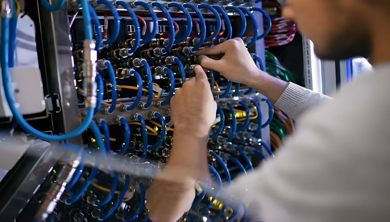
Professional installation teams ensure consistent quality across thousands of cable terminations
3.2 Cable Deployment
3.2.1 Fiber Deployment
Fiber deployment is the most technically demanding process and requires specialized handling:
Backbone Fiber Deployment (MPO Pre-terminated System):
- Use fiber protection tubes and pulling grips to avoid compression damage
- Pulling force not exceeding 100N for 12-fiber MPO cables
- Bend radius no less than 30mm (OM4) during installation
- Clean end-faces immediately before connection, install dust caps when not connected
Horizontal Fiber Deployment:
- Deploy according to port mapping table to avoid misrouting
- Separate fiber and copper cable pathways to prevent crushing
- Secure every 1.5 meters with appropriate cable ties or Velcro
- Reserve sufficient slack (1-2 meters) at each end for future moves
3.2.2 Copper Cable Deployment
Copper cable deployment has strict requirements to maintain performance:
- Use pulling mesh sleeves or pulling eyes, avoid direct pulling on jacket
- Pulling force not exceeding 50N (Cat6A) to prevent conductor stretch
- Avoid parallel routing with power cables; maintain minimum 30cm separation
- Do not exceed maximum pull length of 90 meters for horizontal runs
3.3 Termination and Cable Management
3.3.1 Fiber Termination Methods
| Termination Method | Typical Loss | Application | Pros/Cons |
|---|---|---|---|
| Pre-terminated Fiber | 0.20-0.35 dB | Backbone connections | Fast, consistent quality, higher material cost |
| Fusion Splicing | 0.05-0.10 dB | Permanent connections | Lowest loss, requires expensive equipment |
| Mechanical Splicing | 0.20-0.50 dB | Temporary repairs | Quick, higher loss, no fusion splicer needed |
3.3.2 Copper Cable Termination
For shielded systems (Cat6A S/FTP), proper termination is critical:
- Strip outer jacket accurately (approximately 30mm)
- Fold shield layer backward and secure to drain wire
- Maintain pair twist; untwist no more than 13mm at termination
- Crimp according to T568B standard (verify with facility standard first)
- Ensure shield contacts patch panel metal housing for proper grounding
3.3.3 Cable Management Standards
Good cable management affects both aesthetics and operational efficiency:
Cable Management Principles
Direction: Right-in left-out or top-in bottom-out, maintain consistency throughout
Independence: Each patch cord routed independently, no crossing or wrapping
Bend Radius: Greater than 4 times cable diameter for copper, 10 times for fiber
Securing: Use Velcro straps, avoid overtightening with zip ties
Service Loop: Reserve maintenance length (approximately 30cm) at each end
Labels: Clearly readable, facing consistent direction, protected from wear
3.4 Labeling and Documentation
3.4.1 Label Coding Standards
Unified label coding is the foundation of large campus operations and enables rapid troubleshooting:
Example Coding Standards
Cabinet Number: DC1-A-01 (Data Center 1 – Zone A – Cabinet 01)
Patch Panel Number: PD-DC1-A-01-01 (Patch Panel – Location – Sequence)
Port Number: P-DC1-A-01-01-01 (Port – Patch Panel Location – Port Number)
Cable Number: C-DC1-A-01-01-01-DC1-B-02-02-05 (Cable – Origin – Destination)
3.4.2 Documentation Management
Complete documentation is an essential part of project delivery and ongoing operations:
- Port mapping table (Excel/database with search capability)
- Network topology diagram (updated as-built)
- Cabinet layout diagram (including device positions and power connections)
- Test reports for all cables (linked to cable IDs)
- Change record form (template for tracking all modifications)
4. Testing and Acceptance Phase
4.1 Fiber Testing
4.1.1 Optical Power Testing
Test each fiber link using an optical power meter to verify end-to-end performance:
| Test Item | Standard Value | Test Equipment |
|---|---|---|
| Insertion Loss (OM4) | ≤ 1.5 dB per 100m + connectors | Optical Power Meter |
| Return Loss (UPC) | ≥ 45 dB | Optical Power Meter |
| Return Loss (APC) | ≥ 55 dB | Optical Power Meter |
| Polarity Verification | Correct connectivity A→B | Visual Fault Locator |
4.1.2 OTDR Testing
For backbone fiber, use OTDR to identify and locate any anomalies:
- Test wavelength: 850nm/1300nm (multimode), 1310nm/1550nm (single-mode)
- Test pulse width: Selected based on fiber length
- Analyze event points: Splice points, connectors, macrobends, breaks
- Store traces: Archive OTDR traces for future comparison
4.2 Copper Cable Testing
4.2.1 Basic Testing
Perform basic testing using a copper cable tester for all links:
- Wire Map (verify pin-to-pin connectivity)
- Length (verify within 100m channel limit)
- Attenuation (verify within limits)
- Near-End Crosstalk (NEXT)
- Equal Level Far-End Crosstalk (ELFEXT)
4.2.2 Certification Testing
For Cat6A and higher performance cables, complete certification per ANSI/TIA-568.2-D:
Certification Test Items
Wire Map: Correct pin assignment and continuity
Length: ≤ 100m permanent link, ≤ 90m horizontal cable
Propagation Delay: ≤ 555ns
Delay Skew: ≤ 50ns
Insertion Loss: At all frequency points up to 500MHz
NEXT, PS NEXT: At all frequency points
ACR-F, PS ACR-F: At all frequency points
Return Loss: At all frequency points
DC Resistance: ≤ 25Ω per 100m
4.3 Acceptance and Delivery
4.3.1 Acceptance Checklist
| Category | Inspection Items |
|---|---|
| Physical Installation | Cabinets secure and level, patch panels aligned, cables neatly routed, labels complete |
| Test Reports | All fiber tests passed, all copper tests passed, OTDR traces archived |
| Documentation | Port mapping table complete, topology diagram as-built, cabinet layouts accurate |
| Outstanding Issues | Issue list documented with resolution plan and timeline |
4.3.2 Delivery Training
Provide comprehensive training to customer operations team:
- Cabling system architecture overview and design rationale
- Label coding standards and port mapping navigation
- Daily operation and maintenance procedures
- Troubleshooting flowcharts and escalation procedures
- Documentation update standards and change management
5. Operations and Maintenance Phase
5.1 Daily Inspections
Large data center campuses require regular cabling inspections to maintain reliability:
| Frequency | Inspection Content |
|---|---|
| Daily | Room temperature/humidity, loose patch cords, cabinet door seals |
| Weekly | Cable tidiness, label integrity, cable manager condition |
| Monthly | Patch panel port utilization, tray load, spare cable inventory |
| Quarterly | Optical power retesting (sample), copper performance sampling |
5.2 Change Management
All cabling changes must follow formal change management processes:
Change Management Process
1. Request: Submit change request with reason, impact scope, and rollback plan
2. Approval: Change approval based on impact level (P1/P2/P3)
3. Execution: Execute change during approved window, fill out change record
4. Verification: Test and verify change success
5. Documentation: Update port mapping table and as-built diagrams
6. Archive: Archive change record for audit trail
5.3 Incident Handling
Establish rapid response incident handling mechanisms with clear escalation paths:
| Priority | Definition | Response Time | Resolution Target |
|---|---|---|---|
| P1 | Business impact, service down | < 15 minutes | < 4 hours |
| P2 | Redundancy impact, degraded service | < 2 hours | < 24 hours |
| P3 | Alert only, no immediate impact | < 24 hours | < 1 week |
6. Key Success Factors
Summary: What Makes Large Campus Installations Successful
Planning: Invest 20-30% of project time in thorough planning and design
Standards: Follow TIA-942-B and ISO/IEC 11801 standards consistently
Documentation: Maintain real-time documentation updates during installation
Testing: Test 100% of links; no exceptions for "simple" connections
Training: Ensure operations team is trained before handover
Modularity: Design for change; assume future expansion will occur
Related Articles
- How AI Infrastructure Is Reshaping Data Center Cabling Requirements — Understanding the unique demands of AI workloads on network infrastructure
- Structured Cabling for AI Data Centers: What Is Changing — Key differences between traditional and AI-optimized cabling designs
- MPO Fiber Solutions for Data Center and High-Density Cabling — Selecting the right MPO configuration for your deployment
- How to Choose the Right Fiber Type: Singlemode vs Multimode — OM3/OM4 vs OS2: matching fiber type to link speed and distance

AMPCOM Technical Team
Industry experts with 15+ years in enterprise network infrastructure
Planning a large-scale data center deployment?
Our team offers free consultation and customized cabling solutions for hyperscale and enterprise data centers.
Get Free Consultation

