
Cable Certification Decoded: Fluke, OTDR, NEXT & ACR-F Testing Guide
Published:Executive Summary: A cable that boots a link is not a certified cable. The gap between "lights up" and "meets TIA/ISO standards with documented margin" is where silent network failures breed. Certification — with a Fluke DSX on copper and an OTDR on fiber — is the only process that proves every meter of your installed plant will carry the rated bandwidth for its rated life. This guide unpacks every major test parameter, every common failure mode, and every pass/fail threshold that determines whether your installation survives its next audit.
By the end, you will understand the difference between verification, qualification, and certification — and why confusing them is the single most expensive mistake in structured cabling.
Quick Navigation
- 1 Verification vs Qualification vs Certification
- 2 Fluke DSX Copper Certification: Full Parameter Breakdown
- 3 NEXT: The Parameter That Fails First
- 4 ACR-F (Formerly ELFEXT): The Length-Normalized Test
- 5 OTDR Fiber Testing: Reading Traces Like a Pro
- 6 Certification Limits by Cable Category
- 7 Permanent Link vs Channel: Which Test to Run
- 8 Top 6 Certification Failure Modes & Fixes
- 9 Real-World Case Studies
- 10 Building a Certification-Ready Installation Process
- KQ Key Questions & Answers

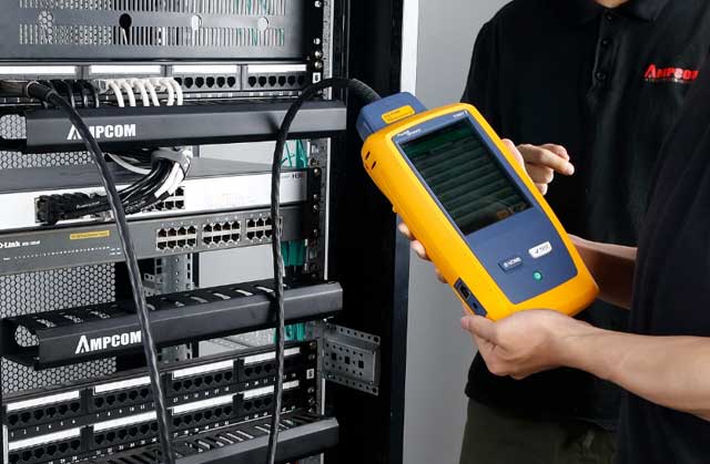
A Fluke DSX-8000 performs a full-parameter autotest — certification is the only testing tier that validates manufacturer warranty (Credit: AMPCOM)
1. Verification vs Qualification vs Certification: Know the Difference
Most network teams use the word "test" loosely. In the structured cabling world, testing falls into three legally and technically distinct tiers — and conflating them is the root cause of most post-installation network problems.
1.1 Verification (Tier 0)
Verification answers one question: are the pins connected in the right order? A wire map tester — even a $50 continuity checker — performs verification. It checks for opens, shorts, miswires, and split pairs. It does not measure frequency-dependent parameters, does not test bandwidth, and cannot predict whether a link will carry 10GBASE-T. Verification is appropriate for troubleshooting a dead drop, not for accepting a new installation.
1.2 Qualification (Tier 1-minus)
Qualification adds throughput testing — it sends actual Ethernet frames (or a bit-error-rate test pattern) across the link and measures whether the cable can sustain a given data rate. A qualifier like the NetAlly LinkRunner or Pockethernet can tell you a link "supports 10G" but cannot tell you why it barely passes or whether it will still pass after two years of connector oxidation. Qualification is useful for pre-certification troubleshooting and move/add/change work; it is not a substitute for certification in new construction or for warranty validation.
1.3 Certification (Tier 1 and Tier 2)
Certification is the only testing tier that produces a legally defensible, standards-referenced report. A certifier — Fluke DSX-5000/8000 for copper, or OTDR plus light source/power meter for fiber — sweeps every parameter across the full frequency band and compares every value against published TIA-568.2-D or ISO/IEC 11801 limits. Certification is what cable manufacturers require to honor their 25-year performance warranties. It is non-negotiable in healthcare (HIPAA physical layer documentation), finance (MiFID II latency SLAs), and any AI/ML data center build.
| Testing Tier | What It Measures | Instrument Cost | Warranty Valid? | When to Use |
|---|---|---|---|---|
| Verification | Wire map, continuity, length (TDR) | $50–$500 | No | Troubleshooting, day-one turn-up |
| Qualification | Throughput, SNR, BER pattern test | $700–$2,500 | No | Pre-cert troubleshooting, MAC work |
| Certification | Full frequency sweep: NEXT, PS-NEXT, ACR-F, PS-ACR-F, RL, IL, delay, skew, resistance, TCL, ELTCTL | $8,000–$15,000+ | Yes | New construction, warranty, compliance |
2. Fluke DSX Copper Certification: Full Parameter Breakdown
The Fluke DSX Series — DSX-5000 (up to 1000 MHz, Cat 6A/Class FA) and DSX-8000 (up to 2000 MHz, Cat 8/Class I/II) — is the de facto field certification standard. A single autotest (6–15 seconds) measures every parameter below on every pair and compares each value against the selected standard's limit line.
| Parameter | What It Measures | Why It Matters | Typical Fail Root Cause |
|---|---|---|---|
| Wire Map | Pin-to-pin continuity, opens, shorts, split pairs, crossed pairs, reversed polarity | Fundamental; any fault here invalidates all other tests | Wrong T568A/B at one end, punch-down error |
| Insertion Loss (IL) | Total signal attenuation from transmitter to receiver, in dB | IL accumulates with cable length, connector count, and temperature; too high and the receiver cannot read the signal | Cable too long, poor-quality connectors, damaged cable |
| NEXT | Pair-to-pair crosstalk measured at the near end (dB, higher is better) | The single most common certification failure. Excess untwist at the termination point dominates NEXT performance | Untwist > 13 mm at jack, wrong punch-down tool, zip-ties compressing cable |
| PS-NEXT | Sum of crosstalk from all three other pairs into one pair (dB) | More stringent than pair-to-pair NEXT; fails when individual pairs pass but cumulative crosstalk exceeds limit | Counterfeit cable with degraded pair geometry over long runs |
| ACR-F | Far-end crosstalk normalized for length (dB, higher is better) | Indicates usable signal margin at the receiver after cabling impairments; low values cause bit errors under load | Physical cable damage (crush, kink, stretch), poor far-end termination |
| PS-ACR-F | Power sum of all far-end crosstalk normalized for length | The cumulative far-end performance metric; fails on damaged or low-quality cable in high-pair-count bundles | Same as ACR-F, compounded by bundle heating |
| Return Loss (RL) | Signal reflected back to the transmitter due to impedance mismatches (dB, higher is better) | Poor RL causes transmitter instability and signal degradation; critical for full-duplex 1000BASE-T and above | Impedance mismatch at connectors, tight bends, cable deformation |
| Propagation Delay | Time for signal to travel end-to-end (nanoseconds) | Excessive delay violates Ethernet collision domain timing; critical for CSMA/CD in industrial networks | Excessive cable length or velocity-of-propagation mismatch |
| Delay Skew | Propagation delay difference between fastest and slowest pair | Excessive skew (> 50 ns for 1000BASE-T) causes the receiver to misalign parallel bit streams | Non-uniform pair twist rates, damaged pair, manufacturing defect |
| DC Loop Resistance | Total conductor resistance end-to-end (ohms) | High resistance wastes PoE power as heat; TIA TSB-184-A defines channel limits for PoE Type 3/4 | CCA (copper-clad aluminum) cable, undersized conductors, corroded contacts |
| TCL / ELTCTL | Transverse Conversion Loss and Equal-Level Transverse Conversion Transfer Loss | Measures the cable's immunity to external EMI; critical in industrial Ethernet (PROFINET, EtherNet/IP) | Poor shield termination, manufacturing defect in pair balance |
3. NEXT: The Parameter That Fails First
Near-End Crosstalk is the most frequently failed certification parameter, and the physics behind it explains why.
3.1 The Physics of NEXT
When a signal travels down one twisted pair, its electromagnetic field radiates outward. Adjacent pairs within the same cable jacket act as unintended antennas, inductively and capacitively coupling a portion of that signal. NEXT measures this coupled signal at the same end where the original signal was injected — hence "near-end." The key relationship:
NEXT degrades with frequency. At 50 MHz, a Cat6 cable may show 40 dB of NEXT (only 0.01% of the transmitted signal couples across). At 250 MHz, the same cable pair shows only about 33 dB (0.05% coupling). Higher bandwidth cables — Cat 6A at 500 MHz, Cat 8 at 2000 MHz — fight a progressively harder battle against electromagnetic physics.
3.2 NEXT vs PS-NEXT
Pair-to-pair NEXT measures one disturbing pair at a time. But in a four-pair cable, three other pairs can simultaneously generate crosstalk into the pair under test. PS-NEXT (Power Sum NEXT) mathematically combines all three contributions:
| Parameter | Cat5e (100 MHz) | Cat6 (250 MHz) | Cat6A (500 MHz) | Cat8 (2000 MHz) |
|---|---|---|---|---|
| NEXT (worst pair) | 35.3 dB | 33.1 dB | 26.1 dB | ~20 dB* |
| PS-NEXT | 32.3 dB | 30.2 dB | 23.2 dB | ~17 dB* |
*Cat 8 Class II limits at 2000 MHz are approximate; refer to ISO/IEC 11801-1 Ed. 2.0 for exact values. All values shown as minimum positive dB margin for a permanent link per TIA-568.2-D.
3.3 What Causes NEXT Failures
In over 80% of field cases, NEXT failure traces to one root cause: excess conductor untwist at the termination point. The precise twist rate of each pair is engineered to cancel electromagnetic coupling. When an installer untwists more than 13 mm (Cat5e) or 10 mm (Cat6/6A) to dress conductors into a jack or patch panel, that untwisted segment becomes a crosstalk antenna. The fix is almost always re-termination with disciplined untwist control — using the manufacturer's termination tool and keeping the twist intact as close as physically possible to the IDC contact point.
NEXT Troubleshooting Checklist
- Is the failure at the near end or far end? Run the test in both directions; the DSX HDTDX fault-location graph pinpoints which end is the problem
- Untwist length: Cat5e max 13 mm, Cat6 max 10 mm, Cat6A max 8 mm, Cat8 max 3 mm from termination point
- Punch-down tool: Use the jack manufacturer's specific tool; generic impact tools leave inconsistent IDC gas-tight connections
- Cable ties: Never cinch zip ties tight on Cat6A or Cat8 cable; use Velcro at 300-450 mm intervals, loose enough to slide
- Patch cord quality: A Cat5e patch cord plugged into a Cat6A link will drag the entire channel's NEXT performance down to Cat5e levels
- Split pair: Wire map test must run first — a split pair will produce a NEXT reading that looks deceptively "good" because the pairs are miswired
4. ACR-F (Formerly ELFEXT): The Length-Normalized Test
If NEXT is about what leaks back toward the transmitter, ACR-F is about what leaks forward to the receiver — and why longer cable runs are disproportionately vulnerable.
4.1 The Formula
ACR-F = FEXT − Insertion Loss
FEXT (Far-End Crosstalk) is the crosstalk measured at the opposite end from the transmitter. Insertion Loss is the signal attenuation over the cable length. Subtracting IL from FEXT normalizes the measurement for cable length, so a 30-meter link and a 90-meter link can be compared on the same dB scale.
Consider two links built from identical Cat6A cable:
- 30-meter link: FEXT = 55 dB, Insertion Loss = 11 dB → ACR-F = 44 dB
- 90-meter link: FEXT = 40 dB, Insertion Loss = 33 dB → ACR-F = 7 dB
Without the insertion loss subtraction, the raw FEXT values (55 vs 40 dB) would misleadingly suggest the shorter link has far worse crosstalk. With normalization, you immediately see the longer link's ACR-F is critically low — the signal arriving at the receiver is barely above the crosstalk floor. The 90-meter link might pass a basic connectivity check but will generate bit errors under sustained 10GBASE-T traffic.
4.2 Why ACR-F Matters for Real Traffic
ACR-F directly translates to signal-to-noise ratio at the receiver. In 10GBASE-T, the receiver must decode a 16-level PAM (Pulse Amplitude Modulation) signal where each voltage level is separated by just 1/128th of the peak-to-peak amplitude. When ACR-F is low, the noise floor — far-end crosstalk plus ambient EMI — overlaps with the signal levels, and the receiver's decision circuit makes errors. These errors trigger TCP retransmissions at Layers 3-4, which show up as "intermittent slowness" that users feel but Tier 1 help desk cannot pin down.
4.3 Naming History: ELFEXT to ACR-F
ANSI/TIA-568-C.2 (2008) formally renamed ELFEXT (Equal Level Far-End Crosstalk) to ACR-F (Attenuation Crosstalk Ratio, Far-end). There is no technical difference — only nomenclature harmonization with ISO/IEC standards. If your test equipment shows "ELFEXT," it is measuring the same physical phenomenon as "ACR-F." Similarly, PS-ELFEXT became PS-ACR-F. When reading older test reports, treat them as identical parameters.
5. OTDR Fiber Testing: Reading Traces Like a Pro
An Optical Time Domain Reflectometer is to fiber certification what an MRI is to medicine — it reveals the internal structure of a link that a simple end-to-end loss measurement (the "blood pressure check" of a light source and power meter) cannot see.
5.1 How OTDR Works
The OTDR injects short laser pulses (3 ns to 1000 ns pulse width) into the fiber at calibrated wavelengths — typically 1310 nm and 1550 nm for singlemode, 850 nm and 1300 nm for multimode. Two physical phenomena return light to the OTDR detector:
- Rayleigh backscatter: Continuous, weak scattering from microscopic density fluctuations in the glass — this produces the downward-sloping baseline on the trace. Its slope (dB/km) is the fiber's attenuation coefficient.
- Fresnel reflections: Sharp reflections at interfaces where the refractive index changes abruptly — connectors, mechanical splices, fiber breaks, and the fiber end face. These appear as upward spikes on the trace.
By measuring the round-trip time of light and dividing by the speed of light in fiber (~2 × 10⁸ m/s, accounting for the core refractive index of ~1.47), the OTDR calculates the exact distance to every event.
5.2 Reading an OTDR Trace: 6 Features
An OTDR trace is a distance-resolved map of every optical event in the fiber link — LSPM testing alone cannot produce this level of fault isolation (Credit: AMPCOM)
| Trace Feature | What It Is | Typical Values | Red Flag |
|---|---|---|---|
| Launch spike | Reflection from the OTDR connector port | −35 to −45 dB reflectance | Dirty OTDR port causes exaggerated spike and extends dead zone |
| Connector pair | Reflection spike + small step down | 0.2–0.5 dB loss, ≥ −40 dB reflectance | > 0.75 dB loss or reflectance > −35 dB: dirty or damaged end-face |
| Fusion splice | Step down with no reflection spike | 0.01–0.10 dB for singlemode | > 0.3 dB: investigate with bidirectional OTDR measurement |
| Mechanical splice | Step down with small reflection | 0.1–0.5 dB loss | > 1.0 dB: index-matching gel may be depleted or misaligned |
| Macrobend | Gradual loss increase over a distance segment | Visible at 1550 nm, invisible at 1310 nm | Any bend loss at 1550 nm exceeding 0.5 dB over 2 meters |
| End of fiber | Large reflection then drop to noise floor | Distance to this point = total fiber length | No reflection at end = fiber is broken without a clean cleave face |
5.3 Dead Zones: The OTDR's Blind Spot
After a strong reflection, the OTDR detector is temporarily saturated and cannot resolve nearby events. Two types:
- Event Dead Zone (EDZ): 1–5 meters — the minimum spacing to distinguish two reflective events as separate peaks. Two LC connectors 2 meters apart on a patch panel may merge into one spike if your EDZ is 3 meters.
- Attenuation Dead Zone (ADZ): 5–20 meters — the distance after which loss measurements become accurate. A fusion splice 8 meters after a patch panel connector will have an unreliable loss reading if your ADZ is 15 meters.
The universal fix: launch and receive cables. A 100–500 meter spool of fiber (the "launch cable") between the OTDR port and the link under test pushes the instrument's dead zone outside the link. A matching receive cable at the far end exposes the last connector in the link — which would otherwise be hidden inside the OTDR's dead zone from the reverse-direction measurement.
5.4 Bidirectional Testing
A splice that measures 0.15 dB from end A might measure −0.05 dB (a "gainer") from end B. The gainer is an artifact — fiber does not amplify light. It occurs because the two fiber segments spliced together have different backscatter coefficients (different glass composition, slightly different mode-field diameter, or different numerical aperture). The true splice loss is the bidirectional average: (0.15 + (−0.05)) / 2 = 0.05 dB. This is why ISO/IEC 14763-3 and TIA-568.3-D mandate bidirectional OTDR measurements for splice acceptance.
6. Certification Limits by Cable Category
The table below consolidates the critical pass/fail thresholds per TIA-568.2-D for permanent link testing across all active copper categories. These are the numbers your Fluke DSX compares against.
| Parameter | Cat5e (100 MHz) |
Cat6 (250 MHz) |
Cat6A (500 MHz) |
Cat8 Class I (2000 MHz) |
|---|---|---|---|---|
| Insertion Loss (max) | 22.0 dB | 32.2 dB | 32.2 dB | 11.2 dB* |
| NEXT (min, worst pair) | 35.3 dB | 33.1 dB | 26.1 dB | ~20 dB |
| PS-NEXT (min) | 32.3 dB | 30.2 dB | 23.2 dB | ~17 dB |
| ACR-F (min, worst pair) | 23.3 dB | 15.3 dB | 9.3 dB | ~22.7 dB* |
| PS-ACR-F (min) | 20.3 dB | 12.3 dB | 6.3 dB | Consult ISO 11801-1 |
| Return Loss (min) | 10.0 dB | 8.0 dB | 6.0 dB | 12.0 dB* |
| DC Loop Resistance (max) | 25.0 Ω | 25.0 Ω | 25.0 Ω | 25.0 Ω |
| Propagation Delay (max) | 498 ns | 498 ns | 498 ns | 498 ns |
| Delay Skew (max) | 44 ns | 44 ns | 44 ns | 44 ns |
Values represent worst-case limits at the maximum specified frequency for permanent link topology. Channel limits are slightly relaxed to account for patch cord contributions. *Cat 8 Class I at 2000 MHz has a 30-meter channel limit, not the typical 100-meter length. Refer to ISO/IEC 11801-1 Ed. 2.0 for exact Class II limits at 4000 MHz.
7. Permanent Link vs Channel: Which Test to Run
One of the most common certification errors is testing against the wrong topology. The distinction matters because the pass/fail limits are different.
| Aspect | Permanent Link | Channel |
|---|---|---|
| What is tested | Fixed cabling only: horizontal cable + connectors at patch panel and work-area outlet (90 m max) | Fixed cabling + equipment cords + patch cords at both ends (100 m max) |
| Test adapter | Permanent link adapter — terminates at the reference plane excluding patch cords | Channel adapter — includes the actual patch cords in the measurement path |
| When to use | New construction acceptance — this is the installer's deliverable. Patch cords are the customer's responsibility | Full system commissioning — validates the actual cables that will carry traffic, including user-supplied patch cords |
| Limits | Tighter limits (no patch cord loss budgeted) | Relaxed limits (additional insertion loss and crosstalk from patch cords is accounted for) |
| Warranty | Required by most cable manufacturers for the 25-year installed cable warranty | Required by some end-user SLAs; seldom required for manufacturer warranty |
Rule of thumb for selecting test mode
- Installation contractor delivering to a general contractor: Permanent Link test. Your scope ends at the jack. The GC or end user provides and tests patch cords separately.
- Design-build firm delivering a turnkey system: Channel test after verifying Permanent Link passes first. This proves the complete signal path including the patch cords you supplied.
- Post-move/add/change troubleshooting: Channel test with the existing patch cords in place to reproduce the exact failure condition the user is experiencing.
8. Top 6 Certification Failure Modes & Fixes
Failure #1: NEXT Fails at the Near End
Root cause: Excess conductor untwist at the jack or patch panel termination — the most common single failure mode in structured cabling.
Fix: Re-terminate the connector with minimal untwist. For Cat5e: under 13 mm. For Cat6: under 10 mm. For Cat6A: under 8 mm. Use the manufacturer's termination tool — a generic 110 punch-down blade on a Cat6A jack produces statistically worse NEXT by 2-4 dB across the band.
Failure #2: Return Loss Fails on Multiple Pairs
Root cause: Impedance discontinuity — tight cable bend near the connector, cable deformed by over-tightened cable ties, or a poorly seated plug-jack interface.
Fix: Inspect the first 300 mm of cable from the connector for physical damage or deformation. Replace any zip ties with Velcro straps. Re-terminate if the cable jacket appears compressed. If failure persists on the same jack across multiple cables, replace the jack — its internal PCB may have a manufacturing defect causing an impedance mismatch at the contact point.
Failure #3: PS-NEXT Fails While Pair-to-Pair NEXT Passes
Root cause: Individual pair-to-pair NEXT values are marginal (passing by 0.5-1 dB each), and their cumulative sum pushes PS-NEXT over the limit. This usually indicates degraded pair geometry over a substantial cable length — the cable was pulled too hard, kinked at multiple points, or is counterfeit.
Fix: Inspect the cable run for damage. Check pull tension during installation (Cat6A max: 110 N / 25 lbf). If no damage is visible, suspect counterfeit cable — genuine Belden, CommScope, Panduit, or AMPCOM cable will not exhibit PS-NEXT failure with healthy pair-to-pair NEXT. Replace the cable run.
Failure #4: ACR-F Fails at the Far End
Root cause: Physical cable damage mid-span (crush, kink, water ingress, stretch) or poor-quality far-end termination combined with high insertion loss.
Fix: Use the DSX HDTDR graph to identify the fault distance. If the impairment is at the far-end connector, re-terminate. If mid-span, inspect that physical location — check for floor-tile compression, conduit damage, or water in underground ducts. Mid-span damage usually requires cable replacement.
Failure #5: Wire Map Shows Split Pair
Root cause: The installer punched down both conductors of a pair to the wrong pin positions (e.g., pair 3 conductors on pins 3 and 6, but the pair is split with one conductor on pin 3 and the other on pin 7). The wire map visually looks correct at both ends (pins 1-8 connect to pins 1-8), but the pairs are miswired internally.
Fix: Re-terminate both ends using T568A or T568B wiring scheme — never mix schemes on the same link. A split pair will pass a simple continuity tester but fail any certifier because the twisted-pair coupling is destroyed. This is the classic "link works at 10 Mbps but fails at 100 Mbps" scenario.
Failure #6: DC Loop Resistance Exceeds 25 Ω
Root cause: Copper-clad aluminum (CCA) cable or damaged conductors. CCA has approximately 55% higher DC resistance than solid copper per unit length because aluminum's conductivity (3.5 × 10⁷ S/m) is well below copper's (5.96 × 10⁷ S/m).
Fix: Replace the cable with solid copper. CCA cable cannot be certified for any TIA category and is explicitly prohibited by the National Electrical Code (NEC) for communications circuits because of fire hazard from resistive heating under PoE loads. There is no "fix" for CCA cable — it is counterfeit material that must be removed.

NEXT and ACR-F measure crosstalk at opposite ends of the link — together they characterize the full electromagnetic coupling profile of the channel
9. Real-World Case Studies
Case Study: Chicago Trading Floor — Certifying 2,400 Cat6A Drops in 14 Days
A proprietary trading firm in Chicago's financial district required 2,400 Cat6A permanent link certifications before their new trading floor could go live. The firm's SLA specified that no link could operate with less than 4 dB of margin on any parameter — far stricter than TIA's minimum pass threshold — because nanosecond-level latency jitter from retransmissions would directly cost trading revenue.
Challenge: The general contractor's electrical sub had installed the structured cabling but had never run a Fluke DSX certifier. Initial self-tests using a $300 wire mapper showed "100% green" across all 2,400 drops. When the commissioning team arrived with DSX-8000 units, 18% of links (432 drops) failed NEXT or ACR-F.
Root cause: The electricians, working under speed pressure, had untwisted Cat6A conductors 20-35 mm at each jack to make termination easier. On the DSX HDTDX graph, the fault was consistently at the workstation jack within the first 2 meters — classic untwist-induced NEXT failure.
Solution: All 432 failing jacks were re-terminated by certified installers using the jack manufacturer's termination fixture, keeping untwist under 8 mm. Re-testing achieved 100% pass with a mean NEXT margin of 7.4 dB across the 2,400-link population.
Outcome: The trading floor went live on schedule with manufacturer-warranted certification. The 432-link rework cost approximately $28,000 in labor and materials — versus an estimated $380,000+ in revenue loss had the floor missed its go-live date.
Case Study: Hyperscale Data Center — OTDR Finds Hidden Macrobend in MPO-12 Trunk
A hyperscale cloud provider's new availability zone required 576 MPO-12 singlemode trunk cables connecting spine switches to leaf switches across four halls. The contractor's LSPM Tier 1 certification showed all trunks passing end-to-end insertion loss within budget.
Challenge: During commissioning, 100GBASE-LR4 transceivers on 14 of the 576 trunks experienced intermittent link flaps — the links negotiated at 100G but dropped every 3-8 hours. The LSPM insertion loss readings were within 0.2 dB of predicted values and gave no indication of a problem.
Root cause: OTDR Tier 2 testing revealed a 1.7 dB macrobend loss at 1550 nm located at 23.4 meters into the trunk — precisely where the cable entered an overhead ladder rack through a tight 90-degree bend. The bend radius was approximately 15 mm, well below the 30 mm minimum for the installed singlemode cable. At 1310 nm, the same bend showed only 0.3 dB of loss — which is why the LSPM, testing at 1310 nm, had not flagged it.
Solution: The affected MPO-12 trunks were replaced and re-routed with proper bend-radius management using horizontal cable managers at the ladder-rack entry point. All 576 trunks were then OTDR-tested bidirectionally at both 1310 nm and 1550 nm.
Outcome: Zero link flaps post-remediation. The provider amended their structured cabling specification to require Tier 2 OTDR certification at both wavelengths for all MPO trunk cables — the LSPM-only acceptance criteria had been masking wavelength-dependent bend losses for months.
10. Building a Certification-Ready Installation Process
Certification is not a post-hoc checkbox — it is a quality system that starts before the first box of cable is opened.
Pre-Installation Checklist
- Verify the cable itself: Cut a 3-meter sample from each master reel and certify it with factory-terminated RJ45 plugs at both ends. If the raw cable fails, the reel is defective or counterfeit — do not pull it.
- Calibrate the certifier: Run the DSX daily reference calibration with the permanent link or channel adapters you will use for the job. A skipped calibration is the fastest route to a false pass.
- Select the correct test standard: TIA-568.2-D Cat6A Permanent Link, ISO/IEC 11801 Class EA Channel, etc. The wrong standard in the project setup menu produces meaningless results.
- Pre-terminate and test 5 representative links: Demonstrate 4+ dB margin on all parameters before mass termination begins. If these 5 links are marginal, improve your termination technique before scaling up.
- Label every link: Use the naming convention specified in the SOW — Floor-Room-Port is the standard hierarchy. LinkWare Live cloud lets you pre-load ID lists from a spreadsheet so testers in the field select from a dropdown rather than typing.
Post-Test Deliverables Checklist
- LinkWare PC report: The industry-standard PDF report with pass/fail summary, per-link parameter plots, and worst-case margin table — accepted by every cable manufacturer for warranty registration
- OTDR traces (Tier 2 fiber): Bidirectional traces at both 1310 nm and 1550 nm (singlemode) or 850 nm and 1300 nm (multimode), with event tables showing every splice and connector loss
- As-built documentation: Floor plans with cable routes, cable IDs, and test results overlaid — required for ISO 9001-compliant data centers
- Raw .flw files: The native Fluke LinkWare project file — never deliver only PDFs; the raw files enable future audits and troubleshooting with full graphical data
- Warranty registration: Submit the certification report to the cable manufacturer within 30 days of completion to activate the 25-year performance warranty

A launch cable eliminates OTDR dead zones — without it, the first and last connectors in the link under test are invisible to the instrument
Key Questions & Answers
Q1: What is the difference between Fluke certification and basic cable verification?
Verification (wire map and continuity) confirms that pins connect correctly — it tells you nothing about bandwidth or signal integrity. Qualification adds throughput and signal-to-noise ratio testing but cannot generate a standards-compliant report. Certification — performed by a Level III/IV tester like the Fluke DSX-5000 or DSX-8000 — sweeps every parameter across the full frequency band (up to 2000 MHz for Category 8), measures NEXT, PS-NEXT, ACR-F, PS-ACR-F, return loss, insertion loss, propagation delay, delay skew, DC loop resistance, and TCL per pair, then compares every value against TIA-568.2-D or ISO/IEC 11801 pass/fail thresholds. Only certification produces a legally defensible report that validates manufacturer warranty. A $50 wire mapper and a $12,000 DSX-8000 are not doing the same job — they are answering completely different questions.
Q2: What does NEXT measure in cable testing?
Near-End Crosstalk (NEXT) measures how much of a transmitted signal leaks from one twisted pair into an adjacent pair at the near end (same end where the signal originates). It is expressed in dB; higher values are better because they mean less crosstalk couples into the neighboring pair. NEXT degrades with frequency — the same cable that shows 44.3 dB at 100 MHz (Cat6) drops to approximately 33.1 dB at 250 MHz — so certification sweeps across the full operating band. Power Sum NEXT (PS-NEXT) aggregates the crosstalk from all three other pairs into one pair and is the parameter that most often fails first in real-world installations because it captures cumulative degradation that individual pair-to-pair measurements mask.
Q3: What is ACR-F and why did it replace ELFEXT?
ACR-F (Attenuation to Crosstalk Ratio, Far-end) is the 2008 ANSI/TIA-568-C.2 replacement name for ELFEXT (Equal Level Far-End Crosstalk). It is calculated as: ACR-F = FEXT minus Insertion Loss. This subtraction normalizes for cable length, so a 30-meter run and a 90-meter run can be compared on the same dB scale. ACR-F is measured 12 times per end (24 measurements total per link) and characterizes how much usable signal remains at the receiver after subtracting far-end crosstalk and cable attenuation. A failing ACR-F usually indicates a physical cable defect — crushed jacket, tight kink, or poor far-end termination — rather than a connector issue. When your Fluke DSX shows an ACR-F failure, look for physical damage mid-span before re-terminating.
Q4: How does an OTDR differ from a light source and power meter?
A light source and power meter (LSPM) measures total end-to-end insertion loss for the entire fiber link — it gives one number in dB. An OTDR sends short laser pulses into the fiber and plots backscattered light intensity against distance, producing a trace that reveals every event individually: connector loss, splice loss, reflectance at each interface, fiber attenuation per kilometer, and the exact distance to every fault. The OTDR can locate a bad splice at 347.2 meters; the LSPM can only tell you the link has too much loss somewhere. Best practice uses both: LSPM for Tier 1 certification (loss/length/polarity) and OTDR for Tier 2 (event-by-event trace analysis per TIA-568.3-D and IEC 61280-4-2). For MPO trunk cables carrying parallel optics, OTDR testing is effectively mandatory — a single high-loss fiber among 12 or 16 parallel lanes can fail the entire channel.
Q5: What are OTDR dead zones and how do I avoid them?
An OTDR dead zone is the distance after a strong reflective event during which the instrument's receiver is saturated and cannot detect or measure subsequent events. The Event Dead Zone (EDZ), typically 1-5 meters, is the minimum spacing needed to distinguish two reflective events as separate peaks. The Attenuation Dead Zone (ADZ), typically 5-20 meters, is the distance after which loss measurements become accurate. The universal mitigation is to use a launch cable (100-500m spool of fiber) between the OTDR port and the link under test, and a receive cable at the far end. These push the OTDR's own blind spots outside the link you are certifying. Without launch and receive cables, the first and last connectors in every link are invisible — and those are the most common failure points in any fiber plant.
Q6: What dB margins should I target for cable certification?
A pass with 1-2 dB of margin on NEXT or PS-NEXT is technically passing but practically fragile — connector oxidation and jacket aging will erode that headroom within 2-3 years, turning a certified link into a trouble ticket. Target 4-6 dB of margin on the worst-case pair for NEXT and PS-NEXT. For return loss, 3+ dB margin is adequate. For insertion loss, maintain at least 20% margin below the TIA limit (e.g., if the Cat 6A permanent link limit at 500 MHz is 32.2 dB, aim for ≤ 26 dB). A solid certification report with healthy margins is what separates an installation you can warranty for 25 years from one you will be troubleshooting within 25 months. When evaluating bids from cabling contractors, ask for the mean and minimum NEXT margin across the last project of similar size — not just the pass rate.
Q7: What is the difference between Permanent Link and Channel testing?
A Permanent Link test covers only the fixed cabling infrastructure — the horizontal cable plus the connectors at the patch panel and work-area outlet, up to 90 meters. It uses permanent link adapters that terminate at a known reference plane excluding patch cords. A Channel test includes the fixed cabling plus the equipment cords and patch cords at both ends, up to 100 meters total. Permanent Link is the standard deliverable for new construction because patch cords are typically the end user's responsibility; Channel testing validates the complete signal path with all cords in place. Permanent Link limits are tighter because no patch cord loss is budgeted. Manufacturers require Permanent Link certification for warranty registration; Channel testing alone will not activate the 25-year cable warranty.
Q8: Do I need to certify fiber links with both LSPM and OTDR?
Per TIA-568.3-D, Tier 1 testing (LSPM) is mandatory for all fiber links; Tier 2 testing (OTDR) is strongly recommended but technically optional unless specified in the project SOW. In practice, every hyperscale data center, financial trading floor, and carrier hotel now requires OTDR traces as part of the closeout package because the OTDR trace is the only document that proves there is no 0.8 dB microbend at 832 meters that the LSPM's single-number loss measurement cannot reveal. For MPO trunk cables — where a single high-loss fiber fails the entire 8-, 12-, or 16-fiber channel — OTDR testing is operationally mandatory regardless of whether the SOW explicitly calls for it. If your SOW says "Tier 1 only," budget for OTDR testing anyway; the cost of finding a bad MPO trunk after commissioning is 10-20 times higher than finding it during acceptance.
About AMPCOM Cable Certification Support
AMPCOM supplies structured cabling systems engineered to pass certification on the first attempt — not after rounds of rework:
- Factory-Pre-Tested Copper Cable: Every master reel undergoes NEXT, PS-NEXT, ACR-F, and return loss verification at the factory using laboratory-grade network analyzers before shipment, with batch test reports available on request
- 100% Interferometer-Verified Fiber Assemblies: Every LC, SC, and MPO/MTP connector end-face is inspected with a 3D interferometer per IEC 61300-3-35, with individual test reports archived by serial number
- MPO Trunk Cables with OTDR Traces: All MPO-12, MPO-16, and MPO-24 trunk assemblies ship with factory OTDR traces at 1310 nm and 1550 nm, bidirectional-averaged per fiber — your Tier 2 documentation starts before the cable leaves our facility
- Pre-Termination Test Reports: For custom-length copper assemblies, AMPCOM provides in-line NEXT and return loss measurements for every terminated connector pair, ensuring field certification margins
- Certification-Ready Cable Grades: Solid bare copper only — no CCA, no copper-clad steel, no recycled conductor material. Every cable meets or exceeds TIA-568.2-D component specifications by 2+ dB across the band
- Technical Support for Certification: Our engineering team assists with test standard selection, LinkWare report interpretation, and warranty registration for all AMPCOM-certified installations
Related Articles
- Why LC Connectors Became the First Choice for Data Center Cabling — The connector density and insertion loss advantages that make LC the standard for SFP+/QSFP28 transceiver interfaces
- Structured Cabling for AI Data Centers: What Is Changing — How AI training cluster topology requirements are driving new fiber counts, MPO-16 adoption, and tighter loss budgets
- 800G and 1.6T Data Center Cabling Trends 2026 — What 800G optical lanes and 200G-per-lambda transceivers mean for connector selection and cable testing requirements
- MPO Fiber Solutions: Choosing 8, 12, or 24 Fibers for High-Density Cabling — MPO fiber count selection, polarity management, and test considerations for 40G/100G/400G parallel optics

AMPCOM Technical Team
Industry experts with 17+ years in enterprise network infrastructure, structured cabling certification, and fiber optic testing
Need certified cabling that passes on the first test?
AMPCOM provides factory-pre-tested copper and fiber cabling systems with batch certification reports. Our engineering team helps with test standard selection and warranty registration for every installation.
Get Expert Certification Support

