
Data Center Cable Pre-Deployment During Steel Erection: From Underground Conduit to Overhead Trays
Published:Executive Summary: When Sabey Data Centers broke ground on its Umatilla, Oregon campus earlier this year, the structural steel team and the cabling crew sat in the same pre-construction meeting. That coordination — not an afterthought — is what separates projects that commission on schedule from ones that spend months and millions correcting mistakes buried under concrete and behind finished walls. This article walks through every phase of structured cabling pre-deployment during structural construction — from underground conduit stub-outs before the concrete pour to overhead tray routing the week the steel frames go up.
Quick Navigation
- 1 Why Cable Planning Must Start at Steel Erection — Not After
- 2 Underground Infrastructure: Sealing the Foundation Before Pour
- 3 Overhead Cable Tray Planning: Strategy Before the Steel Goes Up
- 4 Fiber vs Copper: Making the Call Before the First Cable Lands
- 5 Steel Erection Protection: Temporary Stands, Sleeves, and Dust Defense
- 6 Commissioning Pre-Checks: Catch Problems While You Can Still Fix Them
- 7 Five Costliest Mistakes in Data Center Cable Pre-Deployment
- 8 Q&A: Common Questions from Construction Teams
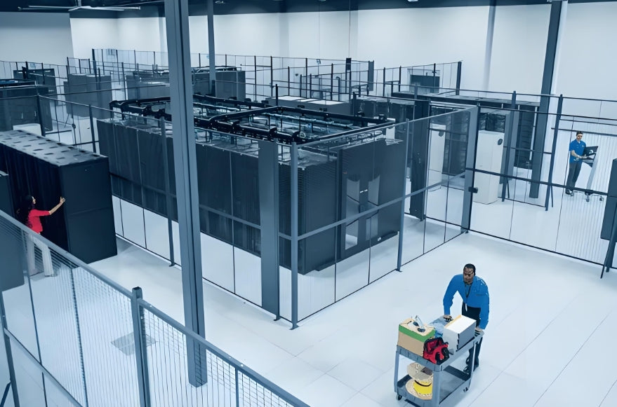
Active data center construction — overhead cable tray and racking infrastructure visible during steel erection phase (Credit: AMPCOM)
Chapter 1: Why Cable Planning Must Start at Steel Erection — Not After
In traditional commercial construction, structured cabling is a post-construction activity. Drop ceilings go in, then the cable guys come. This model breaks down completely in hyperscale data center projects where thousands of fiber runs and copper links must route through pre-engineered cable tray systems that are themselves installed during or immediately after steel erection.
The window for cable pre-deployment work is narrow and unforgiving:
- Underground conduit stub-outs: Must be set before the ground floor slab is poured. Once concrete is in, core drilling costs 10–20× more and creates structural risk.
- Overhead tray hanging: Installed as steel frames are bolted in. The tray routing is set by the structural engineer's layout — it cannot easily migrate mid-build.
- Cable pathway sleeves through steel: Penetrations through structural beams and columns require advance coordination with the steel fabricator. Retrofitting costs $2,000–$8,000 per penetration in hyperscale facilities.
The bottom line: by the time steel topping-out is complete, the cable infrastructure plan should be 80% locked. What follows during the steel erection phase is execution, not design.

High-density data center operations — overhead tray routing visible above the racking infrastructure, showing the interconnected nature of steel and cabling planning
Chapter 2: Underground Infrastructure — Sealing the Foundation Before Pour
Conduit Stub-Outs and Riser Penetrations
Every cable that will ever enter or exit the data center building floor must be routed through conduits stubbed up from the ground floor slab. These stub-ups — typically 4-inch to 6-inch EMT or rigid galvanized conduits — must be positioned, capped, and protected before concrete is poured over the ground floor.
The most common failures at this stage:
- Missing stub-ups: Design changes during early construction mean conduits are not placed where the cable tray system terminates. Result: core drilling through structural slab at $3,000–$6,000 per location.
- Insufficient quantity: Designers underestimate the number of entry points needed for fiber, copper, and cross-connect cables. Data center operators consistently add 30–40% more conduit capacity than initial estimates.
- Wrong elevation: Stub-ups placed too low sit below finished floor level; too high and they obstruct raised floor tile placement.
Recommended Stub-Out Configuration
For a 10MW data center hall with diverse fiber and copper entry points: plan a minimum of 12 × 4-inch conduits for main entry, plus 4 × 6-inch conduits for future expansion. All conduits should extend 150–200mm above finished floor level, capped with reusable foam plugs — not concrete caps — you will need to pull through later.
Ground Rods and Bonding Infrastructure
Data center grounding is not a single ground rod at the service entrance. It is a mesh bonded reference plane that ties into the structural steel, the raised floor pedestal grid, the cable tray system, and all equipment frames. During the foundation phase, grounding bus bars and bonding conductors that will later connect to the cable tray system should be stubbed in and clearly labeled.
Field Tip: Label Everything Twice
During the concrete pour, mud and vibration destroy standard vinyl labels within hours. Use embossed stainless steel tags or stamped steel markers for all underground conduit labels. Photograph the conduit layout from multiple angles before the pour — these photos become your as-built record when nothing else is legible.
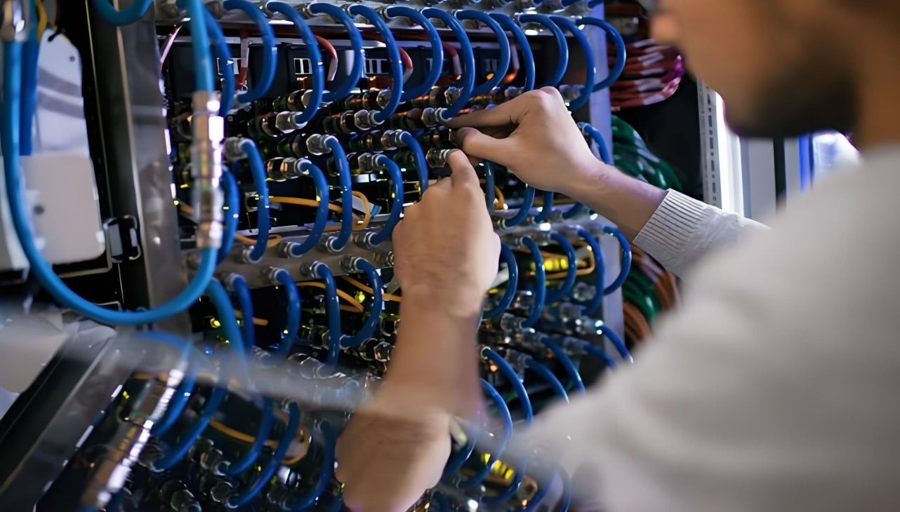
Underground conduit routing and cable testing verification on a data center construction site — every conduit must be labeled and photographed before the pour (Credit: AMPCOM)
Chapter 3: Overhead Cable Tray Planning — Strategy Before the Steel Goes Up
Overhead cable tray installation begins as soon as structural steel columns and beams are in place. The tray routing path — the "highway" that will carry every fiber patch cord and copper jumper in the facility — is one of the most consequential infrastructure decisions in the entire build.
The tray system must accommodate three distinct traffic types simultaneously:
- Inter-row trunk cables: High-count fiber and copper trunks running between row-terminations, typically 12–96 fibers per run
- Cross-connect patches: Individual Cat6A or single-mode fiber patch cords from patch panel to switch, typically 1–3m lengths
- Management cables: Console, KVM, and monitoring cables that may run perpendicular to data traffic
Tray Sizing and Fill Ratio
The cable tray fill ratio — the percentage of cross-sectional area occupied by cables — is governed by TIA-569 and varies by cable type. For data center overhead ladder rack:
| Cable Type | Max Fill Ratio | Recommended Design Fill | Typical Bundle Size |
|---|---|---|---|
| Cat6A / Cat7 / Cat8 copper | 40% (TIA-569) | 30% design target | 24–48 cables per run |
| OM3 / OM4 multimode fiber | 50% | 40% design target | 12–96 fibers per run |
| OS2 singlemode fiber | 50% | 40% design target | 12–144 fibers per run |
| Mixed copper + fiber | 38% blended | 25–30% design target | Calculate by area |
Common Mistake: "We'll Figure Out Fill Later"
AI-driven data centers routinely exceed initial cable count projections by 40–60% within 18 months of first deployment as GPU clusters expand and additional storage nodes are added. Designing tray to the theoretical minimum fill guarantees a mid-life cable spaghetti problem. Always specify tray capacity for 150% of initial projected cable count.
Tray Segregation: The Hot Aisle / Cold Aisle Rule for Cabling
Just as server racks are organized into hot and cold aisles for thermal management, overhead cable tray should mirror this geometry:
- Run copper and fiber trunks above cold aisles or in dedicated "cable alleys" — never directly above hot aisle exhaust paths where temperatures can reach 35–40°C
- Maintain minimum 150mm clearance between cable tray and HVAC ductwork
- Place copper tray on one side of the row, fiber tray on the other — electromagnetic interference from copper can affect fiber signal integrity at high bundle counts
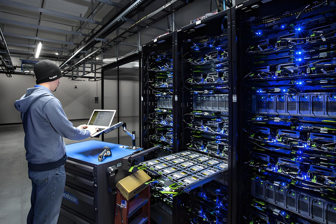
High-density fiber patching in a modern data center — overhead tray routing and bend radius management are finalized during the steel erection phase (Credit: AMPCOM)
Chapter 4: Fiber vs Copper — Making the Call Before the First Cable Lands
The fiber vs. copper decision for a data center is not a single binary choice — it is a topology decision made at multiple levels: inter-row trunk, within-row cross-connect, and server-to-switch uplink. Getting this wrong during steel erection means tearing out tray sections that were engineered for one cable type and replacing them with trays rated for another.
| Application | Recommended Cable Type | Distance Limit | Pre-Deployment Consideration |
|---|---|---|---|
| Inter-row trunk (>30m) | OS2 singlemode fiber (LC/MPO) | 10km+ | Tray must support MPO cassettes; specify minimum bend radius pathway |
| Within-row, <30m | Cat8 copper or OM4 multimode | 30m (Cat8), 100m (OM4) | Cat8 requires more robust tray support; OM4 tolerates tighter bends |
| GPU cluster uplinks | OS2 fiber (400G SR8 / SR4) | 100m OM4, 10km OS2 | GPU clusters require 2–4× more fiber ports per rack than standard compute |
| Storage (NVMe-oF) | Cat8 copper or DAC | Up to 15m (DAC), 30m (Cat8) | DACs eliminate transition points but cannot be field-terminated |
| Management network | Cat6A | 100m channel | Lowest priority for tray space; run in separate management tray |
The Hybrid Approach That Works in Practice
Most hyperscale data centers today deploy a hybrid topology: singlemode fiber for all inter-row and inter-building trunks (future-proofed for 400G/800G), Cat8 copper for within-row connections under 30m (particularly for GPU servers), and OM4 multimode as a cost-effective middle layer. Specify all three tray types in the overhead plan from day one.
For more on selecting the right fiber type for your data center, see our guide: How to Choose the Right Fiber Type: Singlemode vs Multimode.
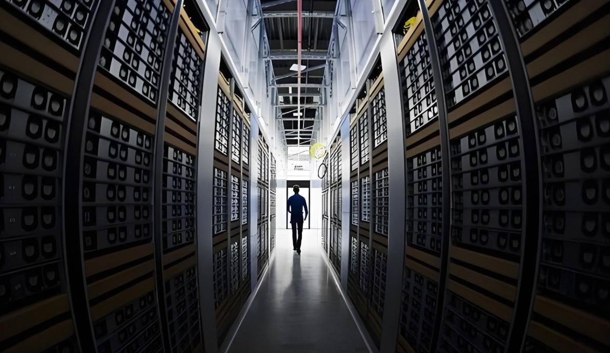
Data room fiber optic cabling with clean overhead tray routing — the result of decisions made weeks earlier during the steel erection phase (Credit: AMPCOM)
Chapter 5: Steel Erection Protection — Temporary Stands, Sleeves, and Dust Defense
Once steel is up and the tray is hanging, the construction phase becomes hostile to cable infrastructure. Wet concrete, grinding sparks, metal swarf, and construction dust will attack any unprotected cable pathway. This is the phase where most cable damage occurs — and most of it is entirely preventable.
Temporary Cable Stands and Placeholder Runs
Where final cable will eventually run but the actual cable installation is weeks away, pull polypropylene rope or lightweight pull tape through the tray as a placeholder. This keeps tray sections identifiable, prevents other trades from filling the space with debris or HVAC components, and makes final cable pulling significantly faster.
Use color-coded pull tape to designate future cable types before they are installed:
- Yellow pull tape: Future copper Cat8 runs
- Blue pull tape: Future singlemode fiber
- Green pull tape: Future multimode fiber
- White pull tape: Management cables
Steel Beam Penetrations and Fire-Stopping
Cable penetrations through structural steel beams — necessary when tray must route through or around a beam web — require fire-rated sleeves and intumescent fire-stopping compounds tested to ASTM E814/UL 1479. These penetrations:
- Must be coordinated with the structural engineer — beam web penetrations reduce load capacity and may require reinforcement plates
- Must be sleeved with fire-rated EMT or rigid conduit — bare cable through a steel penetration is never compliant
- Must be sealed with intumescent collars or pillows on both sides of the penetration
Critical Failure: Unsealed Beam Penetrations
In a recent hyperscale facility in the Pacific Northwest, 23 cable beam penetrations were left unsealed during the construction phase with the intent to "seal them during commissioning." During a fire system test in an adjacent zone, smoke migrated through 19 of the 23 unsealed penetrations, triggering a full smoke zone evacuation and $340,000 in remediation costs. Fire-stop is not optional, and it is not a commissioning task.
Dust and Contamination Control
Construction dust — particularly the fine silica particles from concrete grinding and metal swarf from steel fabrication — is the primary cause of fiber connector failures in newly built data centers. Contaminated fiber end-faces require re-polishing or connector replacement, often after the cable has already been routed through the overhead tray.
Minimum dust control requirements during the cable pre-deployment phase:
- Seal all cable tray open ends with breathable mesh dust covers — not plastic sheeting, which traps moisture
- Require steel grinding operations within 10 meters of open cable tray sections to stop until tray covers are in place
- Conduct fiber end-face inspection (via fiberscope or interferometer) before any connector is mated, regardless of whether the cable was installed in a "clean" zone

Clean overhead cabling installation with proper dust protection measures — fiber end-face contamination during construction is the leading cause of post-commissioning failures (Credit: AMPCOM)
Chapter 6: Commissioning Pre-Checks — Catch Problems While You Can Still Fix Them
The commissioning phase — when IT equipment is racked and powered on — is the last opportunity to correct cable infrastructure errors without dismantling finished infrastructure. A structured pre-commissioning checklist run 2–3 weeks before first power-on will identify 80% of cable-related issues before they become critical path items.
Continuity and Polarity Verification
Before any active testing, verify physical layer continuity on every copper and fiber link:
- Copper: Use a wiremap tester to verify T568A/T568B polarity, pair mapping, and shorts/opens on every Cat6A and Cat8 run before patch panel termination
- Fiber: Use an optical power meter and light source to measure insertion loss on every fiber link before connector mating. Record baseline values in the commissioning log
- MPO/MTP trunks: Verify polarity (Type A/B/Universal) using a fiber optic tracer — polarity errors in 12-fiber and 24-fiber MPO cassettes are among the most common commissioning failures
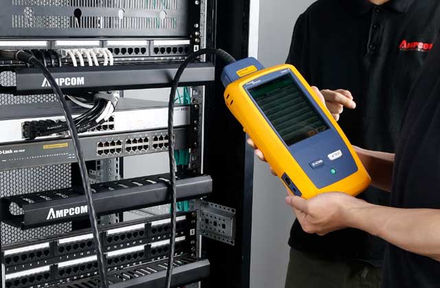
TIA-568 compliant certification testing with AMPCOM equipment — every link must pass before servers are powered on (Credit: AMPCOM)
Bend Radius and Tensile Load Verification
Inspect every fiber run for compliance with minimum bend radius specifications:
| Fiber Type | Min Bend Radius (Loaded) | Min Bend Radius (Installed) | Short-Term Tensile Load |
|---|---|---|---|
| OS2 singlemode | 10× cable OD | 15× cable OD | 270N / 600N |
| OM3 / OM4 multimode | 7.5× cable OD | 10× cable OD | 150N / 300N |
| Cat8 copper | 4× cable OD | 4× cable OD | 110N (20AWG) |
Any fiber run showing bend radius violations at this stage can be re-routed in the overhead tray before server racks are placed underneath. Once racks are populated, tray re-access requires server decommissioning.
Pre-Commissioning Punch List (Abbreviated)
✅ Every copper link passes wiremap and TDR length test
✅ Every fiber link passes insertion loss test (OS2: <0.35dB/km, OM4: <3.0dB/km)
✅ All MPO polarity verified by polarity type and label
✅ All fire-rated penetrations sealed and tagged
✅ Tray fill ratio verified — no section exceeds 40% copper / 50% fiber
✅ Bonding and grounding continuity verified across all tray sections
✅ All labels applied per TIA-606-B and linked to as-built documentation
For a complete guide to reading Fluke certification test reports, see: How to Read Fluke Test Reports: A Priority Guide for Procurement.
Chapter 7: Five Costliest Mistakes in Data Center Cable Pre-Deployment
🚫 Mistake 1: No Dedicated Cable Tray Section for Expansion
Building out tray for exactly the current cable count with zero spare capacity. AI data centers routinely double their fiber port count within 24 months. Retrofitting overhead tray in an occupied data center — with live servers below — costs $15,000–$40,000 per row and requires a maintenance window. Always build 40–50% spare capacity into the initial tray design.
🚫 Mistake 2: Skipping Bonding Continuity at Tray Joints
Cable tray sections are often installed by different trades at different times. When tray sections are joined without bonding jumpers, the tray system becomes an inconsistent ground reference. In data centers running 48V PoE at high currents, this causes ground loops, EMI noise on balanced copper pairs, and unpredictable port errors. Specify bonding jumpers at every tray joint — this is not optional.
🚫 Mistake 3: Specifying Cat8 But Installing Tray for Cat6A Fill Ratios
Cat8 copper cable has a larger outer diameter (~7.4mm vs ~5.5mm for Cat6A) and requires higher bend radius compliance. If the overhead tray was designed around Cat6A fill ratios, Cat8 bundles will exceed fill targets and create bend radius violations. Verify tray compatibility against actual cable OD, not the design spec assumption.
🚫 Mistake 4: Installing Fiber Before Fire-Stopping is Certified
Fire-rated penetrations must be inspected and certified by a licensed fire protection engineer before cable is routed through them. Running fiber through unsealed penetrations creates a non-compliant installation that will fail the final building inspection and may void the data center's insurance coverage.
🚫 Mistake 5: No As-Built Documentation During Construction
The "we'll document it during commissioning" approach systematically fails. By commissioning, conduit positions have shifted under the weight of other trades' work, labels have been damaged, and the personnel who installed the tray are no longer on site. Require weekly as-built updates with photographs during the entire steel erection and tray installation phase — not at the end.
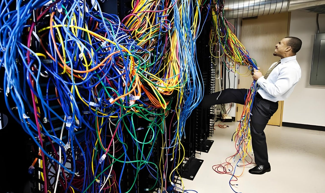
The consequence of skipping pre-deployment planning — cable chaos that could have been prevented at the steel erection stage (Credit: AMPCOM)
Chapter 8: Q&A — Common Questions from Construction Teams
Can we install cable tray and run cables during the steel erection phase, or do we need to wait until topping-out is complete?
Tray installation can begin as soon as primary structural beams are in place and have been inspected. Cable pulling, however, should wait until the building envelope is weather-tight (roof and exterior walls installed) and all wet trades (concrete, drywall finishing, painting) are complete. Cable in a tray during active construction = contaminated cable.
What is the minimum bend radius for fiber optic cable in overhead tray, and how do we enforce it during installation?
OM3/OM4 multimode: 7.5× loaded, 10× installed. OS2 singlemode: 10× loaded, 15× installed. Enforce it by specifying pre-formed fiber guide saddles in the tray at every direction change — these are inexpensive ($8–15 each) and eliminate the guesswork that causes radius violations at field-bent tray transitions.
We have both copper and fiber running in the same overhead tray. Is this a problem?
Running copper Cat8 copper and singlemode fiber in the same tray is standard practice, but the two should be segregated within the tray (copper on one side, fiber on the other, minimum 50mm separation). At high bundle counts (48+ copper pairs), electromagnetic radiation from the copper pairs can induce noise in singlemode fiber at the micro-bending level. For AI data centers running 400G+ fiber, specify dedicated fiber tray or solid partition within shared tray runs.
How do we handle cable pre-deployment when the final server rack layout has not been finalized?
Design the overhead tray system to support the maximum projected rack density, not the current design. The tray layout should be driven by the physical building geometry (column spacing, row length, hot/cold aisle configuration) — not by the current server rack layout, which will change. Leave patch panel and fiber termination positions flexible; lock the tray routing geometry. If the rack layout is truly unknown, run additional conduit stubs and empty pull strings to zones where racks may eventually land.
What cable testing standards apply to data center fiber installations, and what are the pass/fail thresholds?
Data center fiber testing follows TIA-568.3 for premises fiber, with key thresholds: OS2 singlemode insertion loss ≤ 0.5dB per mated connector pair, ≤ 0.35dB/km attenuation; OM4 multimode ≤ 0.5dB per mated connector pair, ≤ 3.0dB/km attenuation. Every permanent link must be tested end-to-end with an OLTS (optical loss test set), not just a visual fault locator.

AMPCOM Technical Team
Industry experts with 17+ years in structured cabling, data center infrastructure, and fiber optic network design
Need a Cabling Partner Who Understands Construction-Stage Coordination?
AMPCOM supplies certified Cat6A, Cat8, and fiber optic cabling solutions with full testing and documentation support for data center construction projects — from 1MW to 100MW+ facilities.
Talk to Our Infrastructure Experts

