
Server Room Cable Management Best Practices
Published:Executive Summary: The ITIC 2024 Hourly Cost of Downtime Report confirms what every data center manager already knows in their gut: a single hour of unplanned outage costs over $300,000 for more than 90% of mid-size and large enterprises. And one of the most preventable root causes? Poor server room cable management.
Tangled cables are not just an aesthetic problem. They obstruct airflow, turn 15-minute troubleshooting sessions into multi-hour cable-tracing marathons, and create a cascade of operational friction that shows up in every MAC (Move, Add, Change) and every audit. This guide delivers a field-tested, TIA-942-C-aligned framework for bringing order to your server room infrastructure — from planning and physical routing to labeling, documentation, and long-term scalability.
Quick Navigation
- 1 The Real Cost of Poor Cable Management
- 2 Plan Before You Pull: Design and Documentation
- 3 Physical Cable Routing: Separation, Bend Radius, Pathways
- 4 Labeling and Color Coding: TIA-606-C Standards
- 5 Cable Management Tools: Managers, Trays, and Fasteners
- 6 Cable Length Management and Service Loops
- 7 Airflow and Cooling: Cable Management's Hidden ROI
- 8 Documentation and DCIM: The Record-Keeping Layer
- 9 Future-Proofing for PoE++, AI, and High Density
- 10 Key Questions Answered

Professional cable management transforms server rooms from operational liabilities into maintainable, audit-ready infrastructure
The Real Cost of Poor Cable Management
Let's quantify what "messy cables" actually costs your organization — because "it looks bad" never convinced a CFO to approve a cable management budget.
Downtime Is the Silent Budget Killer
When an unlabeled cable needs to be traced during an outage, every minute counts. In a well-organized server rack, a technician can visually identify the correct patch cord in under 30 seconds. In a spaghetti rack? That same task consumes 15 to 45 minutes — and sometimes longer if cables are wedged behind equipment or tangled in bundles of identical gray jacket.
Here is what the math looks like at real-world rates:
| Scenario | Time to Trace Cable | Labor Cost ($150/hr) | Business Impact |
|---|---|---|---|
| Labeled, organized rack | 30 seconds — 5 minutes | $1 — $12 | Minimal; MTTR stays in single-digit minutes |
| Unlabeled, tangled rack | 15 — 120 minutes | $37 — $300 | Extended outage; SLA breach possible |
| Multi-cable tracing during major incident | 2 — 4 hours | $300 — $600 | Revenue loss: $300K+/hr unplanned downtime |
This is not theoretical. A major colocation provider documented that implementing structured cable management across 200+ racks reduced their mean time to repair (MTTR) by 62% in the first quarter alone. The ROI on cable management hardware — typically $500 to $2,000 per rack — is measured in weeks, not months.
Airflow Blockage: The Cooling Tax You're Already Paying
Server racks are designed with a specific airflow pattern: cool air enters through the front, passes over components, and exits as hot air through the rear. When cables are allowed to accumulate in front of intake vents or dangle across exhaust paths, they create what thermal engineers call "airflow dams."
Research from data center cooling studies shows that obstructed airflow can reduce cooling efficiency by 15% to 30% in individual racks. Multiply that across a 50-rack server room running 24/7, and the energy cost compound is substantial. Worse, hot spots created by airflow obstruction accelerate hardware degradation — power supplies run hotter, capacitors age faster, and hard drive failure rates climb measurably above baseline.
Data centers consume approximately 1-2% of global electricity, with cooling accounting for 30-40% of operational costs. Optimized cable management that restores proper airflow can reduce cooling requirements by 5-15% — a recurring saving that grows with every kilowatt-hour.
Real-World Impact: Before and After Cable Cleanup
A mid-size financial services firm with 42 racks in a single server room documented these results after a 4-week cable management overhaul:
Before: Average rack intake temperature: 24.2°C (75.6°F). Hot spots in 8 racks exceeding 32°C at exhaust. MTTR for cable-related incidents: 47 minutes average. 3 unplanned outages in previous 12 months traceable to cable issues.
After: Average rack intake temperature: 20.1°C (68.2°F). Zero hot spots above ASHRAE A1 recommended threshold. MTTR: 8 minutes average. Cooling energy consumption reduced by 11%, saving approximately $18,400/year in electricity alone.
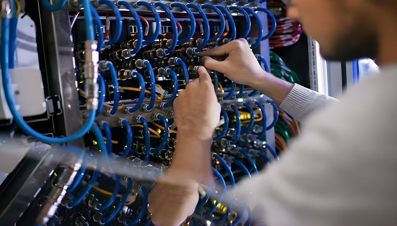
Structured cable pathways with dedicated horizontal and vertical managers keep airflow paths clear and enable fast troubleshooting
Plan Before You Pull: Design and Documentation
The single biggest mistake in server room cable management is treating it as an afterthought — something you "fix later" after the equipment is installed and running. By that point, you are working around live production traffic, and every change carries risk.
Map Your Environment First
Before touching a single cable, create a complete inventory of your physical environment. This baseline is the foundation every subsequent decision depends on:
Server Room Inventory Checklist
Rack elevations: Height (42U/45U/48U), mounting rail position, weight capacityEquipment placement: Switch models, server types, patch panel locations, PDU positionsCurrent cable pathways: Underfloor trays, overhead ladder racks, vertical managersPower and data separation points: Where do power feeds and data cables converge?Cable tray capacity: Current fill percentage and remaining space for growthTemperature and humidity sensor locations: Are sensors placed near known hot spots?Existing labeling: What naming convention is in use (if any)? Is it consistent?Design the Rack Layout as a System
A well-designed rack layout follows a predictable, repeatable pattern that every technician on your team can understand. The industry-standard "1U rule" provides a starting framework:
Rack Unit Allocation Framework
Bottom 2U: Power distribution units (PDUs) — one left, one right for redundancy. These stay at the bottom for stability and because power cables are heavier and shorter than data cables.
Next 4-6U: High-density patch panels in a contiguous block. Place fiber panels first (heavier, less frequently changed), then copper panels above them.
Above each panel row: 1U horizontal cable manager. This is non-negotiable. The 1:1 ratio — 1U of cable management for every 1U of active equipment — is the most reliable predictor of whether a rack will remain maintainable over time. In high-density MPO fiber environments, increase this to 1.5U of management per 1U of equipment to accommodate larger bend radius requirements.
Switch rows: 1U horizontal cable manager above each switch row for top-exit patching. If switches use port-side exhaust (common on higher-end units), ensure managers do not block the airflow path.
Top 4-6U: Vertical cable manager tie-in points, spare patch panels, and 20-30% reserved growth space. Never fill a rack to 100% capacity on day one.
The ANSI/BICSI 002 revision reinforces this with a practical requirement: cabinets in distribution areas (MDA, IDA, HDA) must be at least 800mm wide — roughly 31.5 inches. This replaces the widely-used 600mm (24-inch) racks that physically cannot accommodate proper vertical cable management at the port densities modern networks require. If your racks are 600mm wide, you are already operating with a cabling management deficit that will worsen as you add capacity.
Create Visual Diagrams and Naming Conventions
Documentation is not optional — it is infrastructure. Before any cables are pulled, produce:
- Rack elevation diagrams: Front and rear views showing every U position, equipment model, and cable pathway
- Port mapping table: Every switch port mapped to its corresponding patch panel port, including VLAN assignments and PoE power budget
- Cable route plan: Which pathways carry which cable types, with separation distances from power clearly marked
- Labeling standard document: The naming convention that every cable, port, and device will follow — written down and distributed, not stored in someone's head
A good test: can someone unfamiliar with your server room recreate your exact setup from your documentation alone? If not, your documentation has gaps that will surface during the next emergency.
Physical Cable Routing: Separation, Bend Radius, Pathways
Once the plan exists, physical execution determines whether the design holds up under real-world conditions. Cable routing mistakes are cumulative — a small bend radius violation here, a crushed jacket there — and the result is a cabling plant that degrades unpredictably over time.
Power and Data Separation: The Rule That Never Gets Easier to Ignore
Running power cables parallel to data cables without adequate separation induces electromagnetic interference (EMI). The physics is straightforward: alternating current flowing through a power cable generates a magnetic field that couples into adjacent conductors, corrupting the signal on your data cables. The result is increased bit error rates, retransmissions, and in severe cases, link flaps that trigger spanning-tree recalculations and brief but disruptive network outages.
The minimum separation distances are specified by both TIA and the National Electrical Code (NEC):
| Cable Type Combination | Minimum Separation (Unshielded) | With Partitioned Tray | Notes |
|---|---|---|---|
| Power (110V/220V) & Cat6/Cat6A UTP | 50 mm (2 inches) | Adjacent compartments | Increase to 300 mm for runs >10m parallel |
| Power (110V/220V) & Cat6A S/FTP | 30 mm (1.2 inches) | Adjacent compartments | Shielded cable provides inherent EMI resistance |
| Power (480V 3-phase) & any data | 300 mm (12 inches) | Separate trays required | Higher voltage = stronger magnetic field |
| Fiber optic & power | 0 mm (no separation needed) | Can share trays | Fiber is immune to EMI; still separate for organizational clarity |
The safest approach in any server room: use separate cable trays for power and data, with power cables routed on one side of the rack and data on the other. This eliminates the separation question entirely and makes future cable additions far simpler to plan.
Bend Radius: Where Signal Degradation Lives
Every cable type has a minimum bend radius specified by the manufacturer. Exceeding it does not break the cable in a visible way — it degrades performance in ways that are intermittent and maddeningly difficult to diagnose. A copper patch cord bent too sharply near the connector boot develops impedance discontinuities that reflect signal energy back toward the source, degrading return loss and introducing errors that only appear under high traffic load. A fiber cable bent below its minimum radius creates macrobend attenuation — light literally leaks out of the core at the bend point.
| Cable Type | Minimum Bend Radius (Installation) | Minimum Bend Radius (Long-Term) | Common Violation |
|---|---|---|---|
| Cat6/Cat6A UTP | 4× cable diameter (~25-30 mm) | 4× cable diameter | Tight zip ties near connector boots |
| Cat6A S/FTP | 8× cable diameter (~50-60 mm) | 4× cable diameter | Forcing shielded cable through narrow managers |
| Multimode Fiber (OM4/OM5) | 10× outer diameter (~30 mm for 3mm cable) | 10× outer diameter | Bending at patch panel entry with no strain relief |
| Single-Mode Fiber (OS2) | 10× outer diameter | 10× outer diameter | Wrapping excess slack in loops too tight |
| MPO/MTP Trunk Cable | 10× outer diameter (typically ≥45 mm) | 10× outer diameter | Routing through standard finger ducts designed for copper |
Cable Pathways: Overhead vs. Underfloor
The choice between overhead and underfloor cable routing is one of the most consequential design decisions in any server room, and it cannot easily be changed later.
Overhead cable trays (ladder racks): The dominant choice for new data center builds. Advantages include unrestricted access for moves/adds/changes, no interference with underfloor cooling plenum performance, and easier visual inspection. Overhead routing is particularly important in hot-aisle containment designs, where underfloor space is used exclusively for cold air delivery and should not be obstructed by cables.
Underfloor routing: Common in older facilities and raised-floor environments. The main risk is that cables accumulate in the underfloor plenum, blocking the very airflow the raised floor is designed to deliver. If you inherit a server room with underfloor cabling, prioritize getting cables off the floor and into dedicated trays — every loose cable under the tiles is reducing your cooling efficiency.
Vertical managers: The connection between horizontal and overhead pathways. Vertical cable managers on both sides of each rack provide the "spine" of your routing system. They should have adequate depth (typically 6-8 inches) and be filled to no more than 50% capacity on day one to leave room for growth.
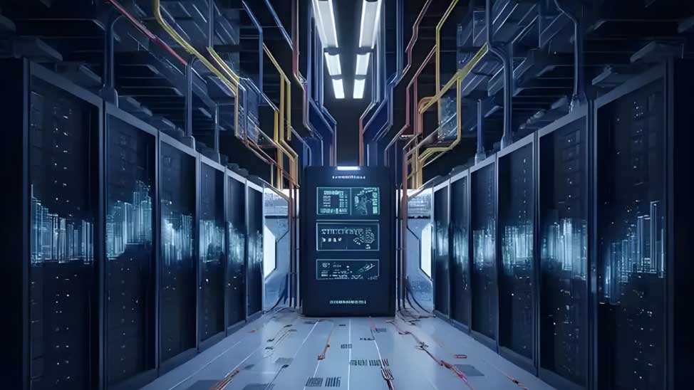
Overhead ladder rack systems with proper capacity planning provide clean, accessible cable pathways that support years of growth
Labeling and Color Coding: TIA-606-C Standards
If there is one practice that separates professional server rooms from amateur ones, it is labeling discipline. An unlabeled cable is a future outage waiting to happen. The standard that governs cable administration is ANSI/TIA-606-C, and while it may seem bureaucratic, following it saves real money every time a technician needs to trace a link.
The TIA-606-C Framework
TIA-606-C defines four classes of administration, from Class 1 (single equipment room) to Class 4 (multi-site enterprise). For most server rooms, Class 2 or Class 3 is appropriate. The core requirement is simple and non-negotiable: every cable, port, patch panel, rack, and pathway must have a unique identifier that links to documentation.
Practical labeling rules that work in the field:
- Label both ends of every cable within 50-100 mm (2-4 inches) of the connector. Anyone looking at either end should immediately know where the other end terminates.
- Use machine-printed labels, never handwritten. Handwriting fades, smears, and varies between technicians. Thermal-transfer or laser-printed labels on industrial-grade wrap-around or heat-shrink tubing survive data center temperatures (rated to at least 60°C / 140°F) and remain legible for years.
- Include source, destination, and port number on each label. A good format: R03-U12-P05 → SW02-P17 tells you this cable runs from Rack 3, Unit 12, Port 5 to Switch 2, Port 17.
- Update labels with every MAC. An outdated label is arguably worse than no label — it actively misleads.
- Conduct quarterly visual audits. Walk the server room and verify that labels are present, legible, and matching documentation. This catches deterioration before it becomes an incident.
Color Coding: Visual Recognition at Wire Speed
Color coding adds a layer of instant visual recognition that labels alone cannot provide. Before a technician is close enough to read a label, they can already identify cable function by color. The TIA-606-C recommended palette has been refined through decades of operational experience:
| Color | TIA-606-C Function | Practical Data Center Application |
|---|---|---|
| Blue | Horizontal Cabling | Standard Ethernet/data connections from patch panels to switches; work area outlets |
| Green | Network Connections | Management and out-of-band access networks; customer-side demarcation connections |
| Purple | Common Equipment | Core switches, routers, PBX, and centralized infrastructure hardware uplinks |
| Yellow | Auxiliary / Alarms | PoE devices (cameras, access points, smart lighting); building automation; security systems |
| Red | Critical / Life Safety | Fire alarm systems, emergency notification, critical infrastructure uplinks — cables you never touch without approval |
| White | 1st Level Backbone | Main cross-connect to intermediate cross-connect backbone cabling; storage network (SAN) connections |
| Orange | Demarcation Point | Central office termination, service provider handoff, test/temporary circuits |
Implementation tip: Do not try to color-code every possible function. Pick 4-6 colors that cover your most common cable roles and enforce them religiously. The goal is clarity under pressure — when a P1 incident is active and tempers are short, a technician who can instantly identify the management network cable by its green jacket is worth their weight in uptime.
For organizations looking to go deeper on labeling strategy, AMPCOM's guide on TIA-606-C color coding and labeling best practices provides detailed implementation templates and field-tested naming conventions.
Cable Management Tools: Managers, Trays, and Fasteners
The right hardware makes proper cable management the path of least resistance. The wrong hardware guarantees that even well-intentioned technicians will take shortcuts when time is tight.
Horizontal Cable Managers
Horizontal cable managers mount directly in the rack between equipment rows and serve as the primary routing channel for patch cords moving between patch panels and switches. They come in two main configurations:
- Finger duct with cover: Individual fingers create separate channels for each cable, preventing tangling and making single-cable removal clean. Covers keep dust out and maintain a professional appearance. This is the preferred type for most server room applications.
- Ring-style (D-rings): Simpler and lower cost, but cables can slip between rings and interleave. Acceptable for low-density racks with infrequent changes, but a false economy in any environment that evolves.
For copper patching, 1U finger duct managers with 45mm x 45mm channel spacing provide adequate room for Cat6/Cat6A patch cords. For fiber, the finger spacing should be wider due to bend radius requirements — some MPO cables need dedicated routing channels.
Vertical Cable Managers
Vertical managers mount on the sides of racks and handle inter-rack patching, backbone cabling, and the transition between horizontal managers and overhead or underfloor pathways. Key specifications:
- Depth: Minimum 6 inches (150 mm) for typical copper and fiber loads; 8-12 inches (200-300 mm) for high-density fiber environments with MPO trunks
- Width: Typically 6-8 inches for double-sided managers (cables enter from both rack sides)
- Fill ratio: Never exceed 50% of cross-sectional capacity. This is not just for future growth — it ensures cables can be inserted and removed without snagging on adjacent bundles
- Attachment points: Velcro anchor rings every 12-18 inches (300-450 mm) along the vertical pathway to prevent cable bundles from sagging
Velcro vs. Zip Ties: Pick Your Fastener Wisely
This is one of the most debated topics in cable management, but the engineering answer is clear:
Use hook-and-loop (Velcro) straps for everything accessible. Velcro distributes clamping force evenly across the cable jacket, does not create pinch points, and — critically — can be released and re-fastened without tools. When a technician needs to add or remove a single cable from a bundle of 48, they can open the Velcro strap, make the change, and re-secure in seconds. Half-inch (12 mm) hook-and-loop straps meet TIA tension limits for cable bundles and outperform zip ties in long-term jacket integrity tests.
Reserve zip ties for permanent, inaccessible infrastructure — backbone cabling inside sealed conduits, cables behind walls, or bundles that will literally never be touched again. Even then, use zip ties with rounded edges and a tension-limiting tool (set to the manufacturer's recommended clamping force) to avoid jacket compression. An over-tightened zip tie on a Cat6A cable can deform the internal pair geometry enough to cause measurable NEXT (Near-End Crosstalk) failures.
Why Velcro Wins: The Physics of Jacket Stress
A standard 4-inch nylon zip tie tightened by hand can exert over 50 pounds of clamping force across a contact area of roughly 0.1 square inches — that is 500 PSI on the cable jacket. A half-inch Velcro strap tightened to the same subjective "snug" feel distributes that force across 2+ square inches for approximately 5-10 PSI. The difference is the difference between a cable that passes certification on day one and a cable that develops intermittent faults six months later.
Cable Trays and Ladder Racks
Cable trays form the structural backbone of your routing infrastructure. For overhead installations, ladder racks provide maximum accessibility and natural convection cooling for the cables themselves. Key installation rules:
- Load capacity: Calculate total cable weight per linear foot, add 25% safety margin, and verify that tray supports and hangers are rated accordingly
- Fill ratio: 40-50% maximum fill at installation, leaving clear space for additions without exceeding the tray's structural limit
- Grounding: All metallic trays must be bonded to the building ground system per NEC Article 250 and TIA-607-C bonding and grounding standards
- Fire stopping: Where trays pass through fire-rated walls, install intumescent firestop systems that maintain the wall's fire rating while allowing cable additions
Cable Length Management and Service Loops
Cable length mismanagement is the single largest contributor to visual chaos in server rooms. The rule is simple: cables that are too short get stretched and fail, cables that are too long become airflow-blocking spaghetti.
The Goldilocks Length Problem
In a typical server rack with top-of-rack switching, the distance from a server port to the switch port it connects to might be 2-4 feet when routed through proper horizontal and vertical cable managers. Yet many data centers are stocked with 7-foot and 10-foot patch cords because "longer is safer." The result: 3-6 feet of excess cable per connection, which is either coiled into messy bundles that block airflow or stuffed into vertical managers until they bulge.
The fix is straightforward but requires discipline:
- Measure actual cable paths — not straight-line distance, but the route the cable must take through managers, around corners, and into the destination port
- Stock standard lengths: 0.5m, 1m, 2m, 3m, and 5m patch cords cover 95% of server room scenarios
- Add 10-15% length margin for service slack — no more
- Enforce length discipline in procurement: Do not buy universal 10-foot cables because they are "cheaper in bulk." The hidden cost in airflow and troubleshooting time dwarfs the per-cable savings
Service Loops: How Much Is Enough?
A service loop is extra cable length coiled at a termination point to permit future re-termination or equipment relocation without re-pulling. The correct amount is 1-2 meters (3-6 feet) at each end, stored neatly in the vertical cable manager or cable tray — never draped across equipment or stuffed behind patch panels.
Common service loop mistakes:
- No loop at all: The cable reaches exactly from point A to point B with zero slack. Any future equipment move requires re-pulling the entire run.
- Loop stored incorrectly: Excess coiled tightly with zip ties, creating inductance issues on copper or macrobend loss on fiber. Always store loops in figure-eight or loose coil patterns.
- Loop in the wrong location: Extra slack at the patch panel end but none at the server end. When the server gets swapped for a different model with a port on the opposite side, the cable no longer reaches.
For more on avoiding these and other costly installation errors, see AMPCOM's breakdown of seven data center cabling pitfalls that cost $5K-$50K per incident.
Airflow and Cooling: Cable Management's Hidden ROI
Cooling is the largest operational expense in most server rooms after electricity for the IT load itself. And cable management has a direct, measurable impact on cooling efficiency — an impact that compounds across every hour the facility operates.
How Cables Disrupt Cooling
Modern servers pull cool air from the cold aisle (front of rack), pass it across internal components, and exhaust heated air into the hot aisle (rear of rack). This simple airflow model breaks down when cables obstruct either the intake or the exhaust path:
- Front intake obstruction: Patch cords dangling in front of server intake vents force servers to work harder to pull air, increasing fan speed and power draw. Worse, obstructed servers often recirculate their own exhaust, creating a dangerous thermal feedback loop.
- Rear exhaust obstruction: Cables piled behind servers, particularly in the hot aisle, create backpressure that reduces exhaust airflow. Hot air accumulates inside the chassis, raising internal component temperatures.
- Cable dams in the cold aisle: Accumulated cable bundles in the underfloor plenum or in front of perforated tiles block cold air distribution to the racks that need it most.
Quantified Impact on PUE
Power Usage Effectiveness (PUE) is the ratio of total facility power to IT equipment power. A PUE of 1.0 would mean 100% of power goes to IT equipment — ideal but unachievable with current technology. The industry average for enterprise data centers hovers around 1.6-1.8, meaning 60-80% overhead beyond IT load, primarily from cooling.
Cable management improvements that restore proper airflow can reduce a facility's PUE by 0.05-0.15. For a 500 kW server room operating at PUE 1.7, a 0.10 PUE improvement saves 50 kW continuously — approximately $43,800 per year at $0.10/kWh. This is infrastructure savings that requires no new equipment purchase, no vendor contract, and no software license. It requires only the discipline to route cables properly.
Practical Airflow Rules for Cable Routing
Airflow-Preserving Cable Management Checklist
Maintain minimum 75 mm (3 inches) clear in front of equipment air intakes — this space is sacredRoute cables horizontally, never vertically across equipment facesUse blanking panels in all unused rack U positions to prevent hot air recirculationKeep cables off the floor in cold aisles — use overhead trays or dedicated vertical pathwaysNever allow cables to drape across perforated floor tiles — each blocked tile starves at least one rackIn containment environments (hot or cold aisle), every cable penetration through the containment barrier must be sealedInstall temperature sensors at rack intake, mid-rack, and exhaust to detect developing hot spots before they become incidentsDocumentation and DCIM: The Record-Keeping Layer
Physical cable management is only half the battle. The other half is maintaining accurate records of what connects where — and keeping those records synchronized with reality.
What to Document (and Why)
The minimum viable documentation package for any server room includes:
| Document | Contents | Update Frequency | Why It Matters |
|---|---|---|---|
| Port Mapping Table | Every switch port ↔ patch panel port ↔ device relationship, including VLAN, speed, and PoE status | After every MAC | Primary troubleshooting reference; answers "what is connected to port 17?" without tracing cables |
| Rack Elevation Diagrams | Front and rear views of each rack with equipment models, U positions, and cable pathway annotations | After every hardware change | Ensures new equipment has adequate space, power, and cable pathway access before installation |
| Cable Schedule | Every cable by ID: type, length, endpoints, installation date, certification test results | When cables are added or replaced | Enables proactive replacement of aging cables and capacity planning for cable tray loading |
| Change Log | Date, technician, description, and rollback plan for every MAC | After every MAC | Audit trail; identifies problematic cables/ports that require repeated intervention |
| Certification Test Reports | Fluke DSX/OTDR test results linked to cable IDs | At installation and after any re-termination | Baseline for future troubleshooting; required for warranty claims and compliance audits |
DCIM: When Spreadsheets Are No Longer Enough
For server rooms with more than 20 racks or 500+ cable connections, spreadsheets become a liability. They do not enforce consistency, they do not provide visual topology, and they rely on a human remembering to update them.
Data Center Infrastructure Management (DCIM) software bridges this gap by providing:
- Visual rack layouts with drag-and-drop equipment placement and automatic capacity calculations (power, weight, U-space, port count)
- Automated cable connectivity tracking — change a connection in the DCIM tool, and the port mapping updates automatically across all dependent views
- Work order generation for planned MACs, ensuring technicians receive clear, consistent instructions and can confirm completion in the system
- Capacity forecasting — predict when you will run out of rack space, power, cooling, or network ports based on current growth trends
- Integration with monitoring systems — correlate physical infrastructure changes with performance data to identify whether a recent MAC coincides with a degradation trend
For smaller environments, a well-structured spreadsheet with enforced naming conventions and a disciplined update process is viable. The threshold for upgrading to DCIM is not rack count — it is whether your current documentation can be trusted during an incident at 3 AM. If you have to walk into the server room to verify what is connected where, your documentation has already failed.
Future-Proofing for PoE++, AI, and High Density
The server room you build today will be asked to support workloads that do not exist yet. Cable management design that works for 2026 must survive the density and power demands of 2030.
Power over Ethernet Is Changing the Thermal Equation
PoE++ (IEEE 802.3bt Type 4) delivers up to 90W per port — enough to power Wi-Fi 7 access points, smart lighting controllers, PTZ cameras, and edge AI inference devices. But higher power means higher cable temperature. When multiple PoE++ cables are bundled tightly together, the combined heat can exceed the cable's rated temperature, degrading insulation and increasing insertion loss.
For PoE-heavy racks:
- Use shielded Cat6A (S/FTP) cabling to handle both the higher current and the EMI from bundled power-carrying conductors
- Reduce bundle sizes: no more than 24 cables per bundle for PoE++ applications
- Increase cable manager fill margins: the heat dissipation requirement means managers that are 30% full on day one may be thermally at capacity once PoE loads are applied
- Consider angled patch panels (45-degree or 60-degree) that direct cables toward the cable manager naturally, reducing bend stress and improving airflow around connectors
AI Workloads: Higher Density, Higher Stakes
AI training clusters are driving rack power densities from the traditional 5-10 kW to 30-120 kW per rack. At these densities, every cable management decision has thermal consequences:
- Fiber dominance: AI fabrics use predominantly fiber (MPO trunks, active optical cables) for 400G/800G interconnects. Fiber cable management requires larger bend radii but generates zero heat, which actually simplifies the thermal picture compared to copper bundles carrying PoE
- Liquid cooling coexistence: In racks with direct-to-chip or immersion cooling, cables must be routed to avoid interference with liquid lines, quick-disconnect fittings, and leak detection systems. This often requires custom vertical manager configurations
- 800mm minimum cabinet width: The TIA-942-C requirement for 800mm-wide cabinets in distribution areas is a direct response to these density trends. A 600mm cabinet cannot physically accommodate the fiber volume, bend radius, and vertical management an AI rack requires
Planning for Tomorrow: The 50% Growth Rule
Every cable tray, every vertical manager, every patch panel port, and every rack U position should be sized with at least 50% spare capacity at installation. This is not wasteful — it is the cheapest insurance policy in the data center. The cost of adding a second overhead ladder rack because the first one is at 100% capacity is 3-5x the cost of installing a single rack with adequate capacity on day one. The same math applies to vertical managers, patch panels, and cable pathways throughout the facility.
Bandwidth growth projections of 50-75% annually, driven by AI, IoT, and cloud migration, mean that a server room at 60% capacity today will be at or near capacity within 18-24 months. The organizations that avoid painful, disruptive recabling projects are the ones that built spare capacity into their infrastructure from the start.
Key Questions Answered
How much does poor cable management actually cost a business?
The direct costs break down into three categories. Extended troubleshooting: unlabeled or tangled cables increase MTTR from minutes to hours, at $150+/hour for skilled technicians. Unplanned downtime: ITIC 2024 data confirms a single hour of outage costs over $300,000 for 90%+ of mid-size and large enterprises. Energy waste: obstructed airflow increases cooling costs by 5-15% — roughly $10,000-$45,000 per year for a typical server room, depending on size. The combined ROI of structured cable management typically recovers its cost within 6-12 months.
What is the right ratio of cable management space to active equipment?
The industry best practice is 1:1 — allocate 1U of horizontal cable management for every 1U of active equipment (switches, servers, patch panels). For high-density environments with MPO fiber trunks or bundles exceeding 48 copper cables per manager, increase to 1.5U of management per 1U of equipment. This ratio is not optional: racks that violate it become unmanageable within 12-18 months of growth. Pair horizontal managers with vertical managers on both sides of the rack, filled to no more than 50% capacity on day one.
Should I use Velcro straps or zip ties for cable bundles?
Use Velcro (hook-and-loop) straps for all accessible cabling. They distribute pressure evenly across cable jackets, do not create pinch points that degrade signal performance, and — critically — can be released and re-secured in seconds when cables need to be added or removed. Half-inch Velcro straps meet TIA tension requirements and outperform zip ties in long-term jacket integrity. Reserve zip ties only for permanent, inaccessible cable bundles (inside walls, sealed conduits), and always use a tension-limiting installation tool to prevent jacket compression.
What TIA standards apply to cable management?
Four key standards govern server room cabling: TIA-942-C (2024) specifies data center infrastructure, including 800mm minimum cabinet width for distribution areas and cable pathway design requirements. TIA-606-C defines cable administration — labeling formats, unique identifiers, color coding recommendations, and documentation requirements. TIA-568-D covers copper cabling performance, including bend radius and termination standards. TIA-569-D addresses pathways and spaces, including cable tray fill ratios, separation distances, and firestopping requirements. Compliance with all four is expected in any professional server room build.
How far apart should power and data cables be routed?
Maintain a minimum of 50 mm (2 inches) between unshielded data cables (Cat6/Cat6A UTP) and 110V/220V power cables for parallel runs. For shielded Cat6A (S/FTP), the minimum separation can be reduced to 30 mm. For 480V three-phase power, increase separation to 300 mm (12 inches) and use separate cable trays. Fiber optic cables are immune to EMI and can share trays with power, but keeping them physically separated aids organization and reduces the risk of accidental power disconnection during fiber maintenance. The safest approach: dedicated cable trays for power on one side of the rack, data on the other.
How often should cable labels be updated and audited?
Update labels with every move, add, or change — no exceptions. An outdated label is worse than no label because it actively misleads. Conduct visual audits at least quarterly: walk each row of racks and verify that every cable has a label at both ends, labels are legible and not faded or peeling, and the information on the label matches the documentation. In high-change environments (colocation facilities, managed service providers), monthly audits are strongly recommended. The cost of an audit — roughly 2-4 hours of technician time per quarter — is trivial compared to the cost of chasing unlabeled cables during an outage.
Does cable management improve sustainability and energy efficiency?
Yes — and this is one of the most underappreciated aspects of cable management. Improved airflow from proper cable routing enables cooling units to operate at higher supply air temperatures (ASHRAE now recommends up to 27°C / 80.6°F for A1 class equipment) and lower fan speeds, directly reducing HVAC energy consumption. Organizations with formal cable management programs typically report 5-15% cooling energy savings. For a 200 kW server room, this translates to approximately $8,700-$26,300 in annual electricity savings at average commercial rates. Cable management is one of the few data center improvements that delivers both operational and sustainability ROI simultaneously.
Related Articles
- Patch Panel Cable Management: Complete Guide for Data Centers and Enterprise Networks — Master rack-level organization with the 1U planning rule, horizontal/vertical manager selection, and service loop discipline that keeps your patch fields maintainable for years.
- TIA-606-C Color Coding and Labeling Best Practices: Reduce MTTR in Moves/Adds/Changes — Field-tested color palettes and labeling templates that cut cable-tracing time by 80%+ during MAC operations and incident response.
- Data Center Cabling Mistakes: 7 Pitfalls, Costs & Fixes (TIA/ANSI-Compliant) — The $5K-$50K-per-incident errors that sabotage even well-designed infrastructure — and exactly how to prevent each one with standards-based fixes.
- Structured Cabling for AI Data Centers: What Is Changing — How AI workload densities are forcing a fundamental rethink of cable pathway design, fiber topology, and rack-level serviceability requirements.

AMPCOM Technical Team
Industry experts with 17+ years in enterprise network infrastructure
Is your server room cabling costing you more than you realize?
Our team offers a free cable management audit and customized infrastructure recommendations — from rack-level organization to facility-wide pathway design.
Get Free Cable Management Audit

