
800G Optical Module Installation Practice: MPO Fiber Patch Cord Selection and Connection Standards
Published:Executive Summary: 800G optical modules represent the fastest-growing segment of data center interconnect, with the global market projected to exceed $26 billion USD by 2027. Yet installation errors—particularly around MPO polarity and fiber type mismatches—account for up to 35% of 800G link failures in first-year deployments. This guide walks through every decision point from module selection to post-installation verification, based on AMPCOM's field experience across 200+ AI data center projects.
Quick Navigation
- 1 Why 800G Changes the Installation Game
- 2 Select the Right 800G Module Form Factor
- 3 Choose the Correct MPO Fiber Type
- 4 MPO Connector Selection — MPO-12 vs. MPO-16 vs. MPO-24
- 5 Master MPO Polarity — The #1 Cause of 800G Link Failures
- 6 Installation Best Practices — The 800G-Specific Rules
- 7 Testing and Verification — The 800G Acceptance Standard

High-density AI data center rack deploying QSFP-DD 800G modules — proper MPO infrastructure planning is essential before deployment begins
Chapter 1: Why 800G Changes the Installation Game
The transition from 400G to 800G Ethernet is not simply a doubling of speed — it fundamentally changes the MPO fiber solutions requirements for data center cabling infrastructure. Previous generations—10G, 40G, and even 400G—could often be serviced with relatively forgiving infrastructure tolerances. 800G is different in three fundamental ways:
- Lane count doubles: 800G DR8/FR8 uses 8 parallel transmit and 8 parallel receive fiber lanes (16 fibers total), compared to 4 lanes at 400G. Polarity errors that were manageable at 400G cause complete link failure at 800G.
- Loss budgets shrink: 800G PSM8 and DR8 modules have total channel loss budgets of 3–4 dB. A contaminated MPO endface that caused marginal performance at 400G will cause complete link failure at 800G.
- Form factor density increases: QSFP-DD and OSFP modules in AI data center racks require higher-density MPO connections, making physical access for cleaning and inspection more difficult than previous generations.
As 800G and 1.6T trends reshape data center cabling, the installation practices that worked for 400G are no longer sufficient. Every decision point — from fiber type to polarity method — must be specified with precision.

High-density 800G deployments require precise MPO infrastructure planning — each rack may contain 1,000+ individual fiber connections
Chapter 2: Select the Right 800G Module Form Factor
Before selecting MPO components, you must know which 800G optical module form factor your switches and routers use. The two dominant form factors — QSFP-DD and OSFP — have different thermal and electrical characteristics, but they share identical MPO-16 requirements for DR8 and FR8 applications.
QSFP-DD vs. OSFP: What It Means for Your MPO Selection
| Specification | QSFP-DD | OSFP |
|---|---|---|
| 800G implementation | QSFP-DD800 (8×100G lanes) | OSFP800 (8×100G lanes) |
| MPO connector required | MPO-16 (16-fiber) for DR8/FR8 | MPO-16 (16-fiber) for DR8/FR8 |
| Backward compatible | QSFP28 (100G) and QSFP56 (200G) | Not directly compatible with QSFP-DD |
| Max power consumption | Up to 28W at 800G | Up to 35W at 800G (higher thermal) |
| Common 800G reach types | DR8 (500m SMF), FR8 (2km SMF) | DR8 (500m SMF), FR8 (2km SMF) |
| Dominant switch vendors | Cisco, Arista, NVIDIA Mellanox, Juniper | Meta-preferred, emerging in hyperscale |
AMPCOM Engineer's Note
Both QSFP-DD800 and OSFP800 use MPO-16 connectors for DR8 and FR8 applications. The physical connector keying is slightly different between the two form factors, but the fiber and MPO-16 patch cord specification is identical. Always verify the module's datasheet for exact MPO gender and polarity requirements — some early QSFP-DD800 modules use MPO-12 instead of MPO-16.

QSFP-DD 800G modules in an AI cluster — the transition to parallel optics demands rigorous MPO specification at every level of the cabling infrastructure
Chapter 3: Choose the Correct MPO Fiber Type — Singlemode vs. Multimode
For 800G deployments, fiber type selection is rarely ambiguous: almost all 800G DR8/FR8 applications require singlemode fiber (OS2/ITU-T G.652.D or G.657.A1). This is a significant shift from 400G where singlemode vs multimode fiber selection was more nuanced for short-reach links.
Why Singlemode Is Mandatory for Most 800G Links
800G modules use wavelength-division multiplexing (WDM) at 1310 nm (DR8 uses 1310 nm PAM4; FR8 uses coherent 1310 nm). At these wavelengths and at 800G line rates (100 Gbps per lane), multimode fiber's modal dispersion makes it unsuitable beyond very short reaches — even with the most advanced OM5 Wideband Multimode fiber and配套的 VCSEL technology.
| Fiber Type | 800G Application | Max Reach at 800G | Typical Use Case | MPO Connector |
|---|---|---|---|---|
| OS2 Singlemode (G.652.D) | 800G DR8 / FR8 | 500m / 2km | AI GPU cluster interconnects, DCI | MPO-16 APC (green) |
| G.657.A1 Singlemode | 800G DR8 / FR8 | 500m / 2km | Data center intra-rack / bend-insensitive routing | MPO-16 APC (green) |
| OM4/OM5 Multimode | 800G SR8 (emerging, expensive) | 50–100m | Very short-reach within racks only | MPO-16 PC (blue) |
| OM3 Multimode | Not recommended for 800G | — | Legacy 400G SR4 only | — |
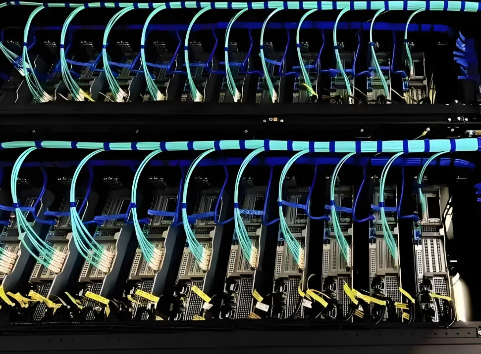
Singlemode OS2 fiber installation for 800G data center interconnects — correct fiber type specification eliminates costly rework during commissioning
Chapter 4: MPO Connector Selection — MPO-12 vs. MPO-16 vs. MPO-24
MPO connector type is determined by the number of fiber lanes your 800G module requires. Getting this wrong means the patch cord physically won't fit or won't support the correct lane mapping — there is no adapter that can bridge a wrong connector type without exceeding your loss budget.
MPO Connector Type Reference for 800G
| MPO Type | Fiber Count | 800G Application | Typical Use | Polarity Method |
|---|---|---|---|---|
| MPO-12 | 12 fibers | 400G SR4 / some early 800G prototypes | Legacy multimode trunks | Type A/B/C |
| MPO-16 | 16 fibers | 800G DR8 / FR8 (primary) | AI data center interconnects | Type B (recommended) |
| MPO-24 | 24 fibers | 1.6T trunking, future-proofing | High-density backbone trunks | Type B |
| MPO-8 | 8 fibers | Some 800G SR8 variants (emerging) | Short-reach, not yet mainstream | Type A |
AMPCOM MPO-16 Selection Checklist
Before ordering MPO-16 patch cords for your 800G deployment, confirm these five specifications:
- Fiber type: Singlemode OS2 or G.657.A1 (not OM4/OM5)
- Polish type: APC (8° angled physical contact) — green boot for singlemode
- Connector gender: MPO-16 Male (pins) on switch side, MPO-16 Female (孔) on module side — verify per port marking
- Jacket rating: OFNR (riser) for overhead tray; LSZH or OFNP (plenum) as required by local code
- Polarity method: Type B (Method B) — straight-through mapping, widely supported across vendors
Q: Can I mix MPO-12 and MPO-16 in the same 800G deployment?
No. MPO-12 and MPO-16 have different form factors and cannot mate. If your 800G DR8 module uses MPO-16, every patch cord, trunk, and adapter in that link chain must be MPO-16. Never use MPO-12-to-MPO-16 adapters in 800G links — the adapter adds insertion loss that will exceed the 3–4 dB budget.

MPO-16 trunk cables in a structured cabling inter-row deployment — correct polarity mapping and connector specification are critical before commissioning
Chapter 5: Master MPO Polarity — The #1 Cause of 800G Link Failures
MPO polarity is the mapping of transmit (TX) and receive (RX) lanes through the MPO connector. A polarity error at 800G means that one or more of your 8 TX lanes land on the far-end RX lanes — causing partial or complete link failure. Unlike 400G where 4-lane polarity errors were sometimes detectable as BER degradation, 800G's tighter loss budgets make polarity errors immediately fatal to the link.
Understanding MPO Polarity Types
There are three TIA-568.3-defined MPO polarity methods. For 800G DR8/FR8, Type B (Method B) is the recommended and most widely supported approach.
| Polarity Type | How It Works | 800G DR8 Suitability | Notes |
|---|---|---|---|
| Type A (Method A) | Straight-through: Pin 1 → Pin 1, Pin 2 → Pin 2, etc. Key-up to Key-up. Requires key-up/key-down pair on one end to flip TX/RX. | ⚠️ Possible but requires gender-flipped connectors — adds ordering complexity | Common for 12-fiber MPO-12 legacy deployments |
| Type B (Method B) | Straight-through fiber mapping with Key-up to Key-down on one end. The connector orientation itself flips TX/RX pairs — no gender flipping needed. | ✅ Recommended for 800G DR8/FR8 | Simpler ordering, fewer installation errors |
| Type C (Method C) | Adjacent-pair flip: Pin 1↔2, Pin 3↔4, etc. Used for duplex conversion. Not applicable for 800G parallel optics. | ❌ Not suitable | Used for SC duplex conversion only |
Case Study: AI Supercomputing Cluster — 800G Link Commissioning Failure and Resolution
Challenge: A hyperscale AI data center deployed 1,024 QSFP-DD800 DR8 links across 64 racks. Initial link bring-up achieved only 67% port-up rate — 336 links failed to establish 800G autocorrelation. Mean time to identify each failure: 45 minutes per link.
Root Cause Analysis:
- 62% of failures (208 links): MPO-16 polarity Type A vs Type B mismatch — modules from two switch vendors had conflicting polarity documentation
- 28% of failures (94 links): Contaminated MPO endfaces (insertion loss > 3.5 dB, exceeding 800G DR8 budget)
- 10% of failures (34 links): Incorrect MPO-16 Male/Female gender specification
AMPCOM Intervention: Replaced 208 MPO-16 patch cords with Type B polarity (key-up/key-down orientation); performed 100% MPO endface inspection and cleaning — 94 connectors required re-cleaning; verified all 1,024 link budgets with an optical power meter before network bring-up.
Result: 1,024/1,024 links operational. Bring-up time: 3 days (vs. estimated 3 weeks with manual troubleshooting). The lesson: specify Type B polarity and 100% inspection at procurement time, not at commissioning time.
Q: How do I verify the polarity of an MPO-16 patch cord I already received?
Visual inspection of key orientation is the fastest method: For Type B, one end has a Key-up connector and the other has a Key-down connector. If both ends are Key-up, it's a Type A cord. You can also use an MPO inspection scope to verify TX lane (odd-numbered pins) and RX lane (even-numbered pins) mapping. AMPCOM's MPO-16 cords are labeled with polarity type and key orientation on the boot.

Post-installation power measurement at both ends of an 800G DR8 link — baseline documentation is essential for future troubleshooting and commissioning verification
Chapter 6: Installation Best Practices — The 800G-Specific Rules
Standard MPO installation practices apply to 800G deployments, but with tighter tolerances. Here are the rules that matter most in the field:
Pre-Installation Inspection: Non-Negotiable
Before any MPO-16 connector is inserted into an 800G QSFP-DD or OSFP module, it must be inspected with an MPO fiber inspection probe. Contamination on even one of the 16 fibers can cause a link failure or trigger the module's protective shutdown — and in an AI cluster with thousands of modules, a single contaminated endface can cascade into significant downtime.
- Inspect at 400× minimum magnification — verify no scratches, pits, or contamination on all 16 fiber endfaces simultaneously
- Clean with MPO-specific cleaning tools — never use bulk fiber cleaning methods; use MPO push-pull cleaners designed for multi-fiber connectors
- Re-inspect after cleaning — cleaning without verification is incomplete
- Use dust caps immediately — never leave MPO connectors uncapped, even during installation
800G MPO Installation Pre-Flight Checklist
- ✅ Verify fiber type: OS2/G.657.A1 singlemode — not multimode
- ✅ Verify polish: MPO-16 APC (green boot) for singlemode
- ✅ Verify polarity: Type B (Method B) — one Key-up, one Key-down
- ✅ Verify gender: Match to module port (check port marking: M/F)
- ✅ Inspect all 16 endfaces with MPO inspection probe
- ✅ Verify no visible contamination after cleaning
- ✅ Verify insertion loss rating: ≤ 0.35 dB per mated pair for OS2
- ✅ Confirm cable routing: maintain minimum bend radius (15× cable OD for OS2)
Bend Radius and Cable Routing for 800G Singlemode
Singlemode fiber is more susceptible to bend loss than multimode, especially at 1310 nm wavelengths used by most 800G DR8 modules. Macro-bend loss in OS2 fiber at 1310 nm can add 0.5–2 dB of loss in a tight-radius bundle, eating directly into your 3–4 dB total loss budget.
| Installation Scenario | Minimum Bend Radius (OS2) | Risk if Exceeded | Mitigation |
|---|---|---|---|
| Short-term (during installation) | 10× cable outer diameter | Transient loss, no permanent damage | Use cable guides and spreaders |
| Long-term (installed state) | 15× cable outer diameter | Permanent increased attenuation | Use bend-insensitive G.657.A1 fiber |
| Tight routing (patch panels) | 30mm minimum | Significant bend loss at 1310 nm | Specify G.657.A1 or route around bend |
| Rack exit and entry | 25mm minimum | Cumulative loss from multiple bends | Use flexible boot MPO connectors |
Power Measurement Before Link Bring-Up
Never rely solely on the link-up indicator light. Before declaring an 800G link operational, measure optical power at both ends with a calibrated power meter. This takes 30 seconds per link and prevents hours of debugging later:
- Target received power: within module datasheet RX sensitivity + 3 dB margin
- Record baseline power at commissioning — this is your reference for future fault isolation
- Document all measurements in your asset management system linked to rack/port location
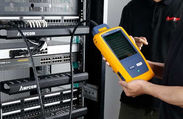
MPO endface inspection with a fiber inspection probe — every fiber in the MPO-16 connector must be verified Grade B or better before insertion into an 800G module
Chapter 7: Testing and Verification — The 800G Acceptance Standard
800G links require stricter acceptance criteria than 400G. Here is the minimum test regime for every 800G DR8/FR8 link — skip any of these steps and you risk hidden failures that emerge only under load.
| Test | Instrument Required | Pass Criterion for 800G DR8 | Why It Matters |
|---|---|---|---|
| Visual endface inspection (all 16 fibers) | MPO fiber inspection probe (400×+) | IEC 61300-3-35 Grade B or better | Detects contamination and scratches that cause link failure |
| MPO insertion loss (IL) | MPO optical loss test set (OLTS) | ≤ 0.35 dB per mated pair (OS2 APC) | 800G DR8 budget is only 3–4 dB total |
| MPO return loss (RL) | OTDR or OLTS with RL option | ≥ 55 dB for singlemode APC | Poor RL degrades PAM4 signal quality and BER |
| Optical power measurement (TX and RX) | Optical power meter + MPO reference cable | Within module RX sensitivity spec | Verifies end-to-end channel loss budget |
| Module bring-up BER test | Switch/router built-in BERT | BER < 1×10⁻¹² (error-free) | Confirms link is fully operational at 800G line rate |
800G DR8 Link Budget Worksheet
Total Channel Loss = MPO Patch Cord A IL + MPO Trunk Cable IL + MPO Patch Cord B IL + Splice/Adapter Losses
Example (passing): Patch A (0.3 dB) + Trunk 200m (0.5 dB) + Patch B (0.3 dB) + 2 adapters (0.2 dB) = 1.3 dB total → Well within 3–4 dB budget. ✅
Example (failing): Patch A (0.8 dB, contaminated) + Trunk (0.5 dB) + Patch B (0.8 dB, contaminated) = 2.1 dB — still within budget, but margin is thin. If trunk is 400m (1.0 dB), total = 2.9 dB — marginal. Add a contaminated endface and you're over budget.
Q: Do I need an OTDR for 800G MPO testing?
Recommended but not mandatory for acceptance testing. OTDR is excellent for locating faults (splices, bends, breaks) but cannot accurately measure end-to-end insertion loss for MPO links. Use an OLTS (optical loss test set) as your primary acceptance instrument, and OTDR as your troubleshooting tool when a link fails. For MPO-16 16-fiber testing, ensure your OLTS supports MPO-16 adapter heads — most legacy MPO testers are MPO-12 only.
Q: What's the minimum BER threshold for accepting an 800G link?
Industry standard is < 1×10⁻¹² (less than 1 error per trillion bits). Most modern switches and routers display real-time BER via CLI or management interface. Accept no link with a measurable error rate above this threshold — BER of 1×10⁻⁸ may show "link up" but will cause throughput degradation under load.

800G data center fiber infrastructure — rigorous pre-commissioning testing ensures all links meet the 3–4 dB loss budget before network bring-up begins
Conclusion: Installation Quality Determines 800G Performance
The transition to 800G Ethernet is the inflection point where installation quality stops being a "nice to have" and becomes a hard requirement. The combination of doubled lane counts, tighter loss budgets, and higher fiber density means that the same level of rigor applied to copper Category 6A certification must now be applied to every single MPO-16 fiber connection in your 800G infrastructure.
Key Takeaways
| Decision Point | Correct Specification | Common Mistake to Avoid |
|---|---|---|
| 800G form factor | Verify QSFP-DD vs OSFP per switch vendor | Assuming all 800G uses the same module type |
| Fiber type | OS2 or G.657.A1 singlemode for DR8/FR8 | Using OM4/OM5 multimode — not suitable for 800G DR8 |
| MPO connector type | MPO-16 APC (green) for 800G DR8/FR8 | Ordering MPO-12 or PC polish — physically incompatible or high RL |
| Polarity method | Type B (Method B) — Key-up to Key-down | Type A without gender-flipped connectors — TX/RX crossed |
| Pre-installation inspection | 100% MPO endface inspection, all 16 fibers, Grade B or better | Skipping inspection because connector looks clean |
| Bend radius | 15× cable OD minimum long-term; G.657.A1 recommended | Treating OS2 like OM4 for bend radius — singlemode is more sensitive |
| Acceptance testing | IL + RL + power measurement + BER test per link | Accepting "link up" as the only pass criterion |
| Documentation | Baseline power readings, test results, port/rack mapping | No records — future troubleshooting has no reference |
For procurement of MPO-16 patch cords, trunks, and installation tools for your 800G data center project, contact AMPCOM's engineering team. We provide factory-tested MPO-16 assemblies with full polarity verification, along with MPO inspection scopes and OLTS instruments for on-site acceptance testing. Every AMPCOM MPO assembly is 100% inspected and shipped with a test report for each individual link.

AMPCOM Technical Team
Industry experts with 17+ years in structured cabling, data center infrastructure, and fiber optic network design
Need help planning your 800G MPO fiber infrastructure?
AMPCOM provides factory-tested MPO-16 assemblies, MPO inspection tools, and full engineering support for 800G data center deployments worldwide.
Talk to Our Cabling Experts

